Automatic Subsewer Drainage In Large Buildings
Description
This section is from the book "American Plumbing Practice", by The Engineering Record. Also available from Amazon: Plumbing: A working manual of American plumbing practice.
Automatic Subsewer Drainage In Large Buildings
(Published In 1895.)
The cellar and basement floors of large city buildings are often at or below the level of the adjacent city sewer, and when this is the case it prevents a gravity drainage of water, sewage, condensations, washings, etc., into it. This is the more likely to be the case as the buildings increase in height, and have proportionately deeper and heavier foundations, the excavations for which it is naturally desirable to utilize for such purposes as underground space may be convenient for. These uses under modern conditions of construction are many and diverse; cellars and subcellars furnish an inconspicuous position for machinery and steam plant, storage, etc ; steam boilers in cellar vaults are more easily reached for repair or renewal, especially if under the sidewalk, than if in the center of the building. In hotels these parts of the structure are used for supplies, stores, wine bins, etc , and in newspaper offices the large presses are installed in the basement, and sometimes the typesetting and stereotyping departments as well are below the street level.
When the foundations are on piles it is a desideratum that the timber should not extend above permanent ground-water level; indeed in some cases it has been planned to artificially irrigate the subsoil for the benefit of the piles, so that the cellar floor and walls are likely to be exposed not only to certain moisture, but to possible hydraulic pressure, which may readily penetrate ordinary masonry or water-proofing. Beside this, the lowest parts of the steam and sewerage systems are likely to fall below the flow line of the street sewer, and thus several causes may contribute to deposit waste liquid in the cellar that must be mechanically removed and should be constantly disposed of, automatically and with positive certainty. Formerly it has been customary to collect all drainage in a cesspool or tank below the lowest floor, and periodically pump its contents out into the sewer. Objections have been made to this method, and another system has been developed, which consists essentially in collecting the subsewer drainage in air-tight iron vessels into which, as soon as they are filled, air pressure is automatically admitted on top of the liquid,which operates to force it out through a sealed outlet, up and into the sewer above. This method is called the Shone ejector system and was explained fully on page 358 of Volume XXVII. of The Engineering RECORD, where the details and operation of the ejectors and the service in several installations were described. It was adopted for the sewage collection at the Columbian Exposition in Chicago, and has been provided in recent large buildings in Chicago, plans of two of which have been sent to us as typical of improved plant for metropolitan buildings by Urban H. Broughton, Asscc. M. Inst. C. E., Engineer and Manager of the Shone Company, Chicago, From these the following description has been prepared:

Figure 1 is a basement plan of the Chicago Daily News Building, and shows the arrangement of drainage pipes from areas, floor strainers, engines, elevators, and other machinery, etc. (but not including any sewage), emptying into a depressed brick-walled catch-basin, whence it flows to a pair of Shone ejectors, which deliver it to the city sewer at a higher level.
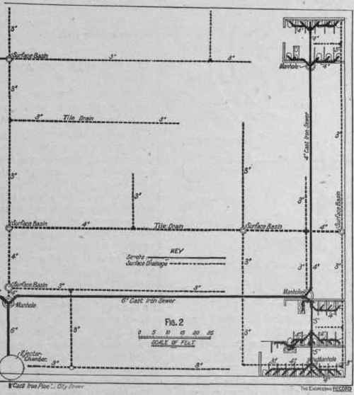
Figure 2 is a plan of the east end of the basement of Marshall Field & Co.'s large new mercantile building, where the sewage from two large sets of water-closets and surface drainage is piped through backpressure valves to catcn-basins whose contents flow to two ejectors that have a capacity of delivery to the sewer of 50 gallons per minute each, and are inclosed in a covered circular, brick-walled, water-tight chamber, about 9 feet in internal diameter and 7 feet deep.
Figure 3 is a conventional vertical sectional dia-dram at Z Z Z Z, Fig. 1, showing the relative vertical positions and features of arrangement of air compressors, receiver, ejectors, and drainage connections to the ejectors and to the sewer.
Figure 4 is a plan and elevation of the two ejectors set in the standard manner, but with their chamber not covered.
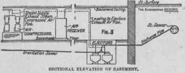
Figure 5 is a diagram of an ejector in section to illustrate its operation. The sewage gravitates through the inlet pipe A and flap valve G into the ejector and gradually rises therein until it reaches the under side of the bell D. The air is thus confined at atmospheric pressure inside this bell, and the sewage continuing to rise around it lifts it, together with the spindle, etc., which opens the compressed-air admission valve E. The compressed air thus automatically admitted into the ejector presses on the surface of the sewage, driving it through the bellmouthed opening in the bottom, and through flap valve H and outlet pipe B, into the iron sewage discharge pipe. When the air pressure is admitted upon the surface of the sewage, the valve G on the inlet pipe A falls on its seat and prevents the fluid escaping in that direction. The sewage passes out of the ejector until its level falls to such a point that the weight of the sewage retained in the cup C, which is no longer supported, is sufficient to pull down the bell and spindle, thereby reversing the valve E, which first cuts off the supply of compressed air to the ejector, and then allows the air within the ejector to exhaust down to atmospheric pressure. The outlet valve H then falls on its seat, preventing back flow from the discharge pipe, and the sewage again flows through the inlet commencing to fill the ejector once more, and so on. The position of the cup and bell is so adjusted that the compressed air is not admitted to the ejector until it is full of sewage, and the air is not allowed to exhaust until the ejector is emptied down to the discharge level. Thus the ejector discharges a specific quantity each time it operates.
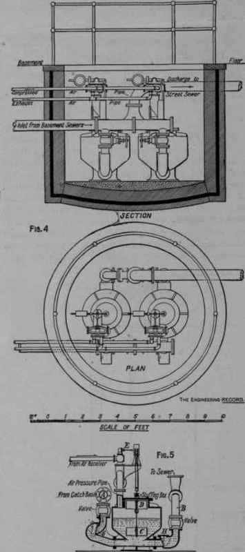
SECTION OF EJECTOR.
In this mechanism the working parts are few and simple and not liable to injury by the sewage. There is no piston friction, the valves do not obstruct the pipes, bottom discharge promotes complete removal of solids and sediment, and the periodic evacuation may constitute a desirable flush. To work the ejector a small air compressor is employed which can be bolted to a wall in a convenient place in the engine-room of the building any distance from the ejector. The compressor delivers air into a tank or receiver and from this the air is conveyed to the ejector by means of a wrought-iron pipe of a small diameter. When steam is turned on to the compressor the whole apparatus is automatic. When the pressure requisite to discharge the sewage is attained the compressor stops, automatically starting up again when the pressure of the air is reduced in the receiver by reason of the discharge of the ejector. The only attendance required is for occasional oiling.
Mr. Broughton writes that " the ejector chamber is generally built of brick, with an asphalt course. The sewers for these building are ordinarily cast-iron sewer pipes, and the subsoil drains are tile pipes laid in the ordinary manner. In nearly all the buildings we put two ejectors of 50 gallons capacity per minute each, although in a few we have put two of 100 gallons capacity each."
Continue to:
My Books

