Part III. - Toilet-Rooms And Details Op Brasswork
Description
This section is from the book "American Plumbing Practice", by The Engineering Record. Also available from Amazon: Plumbing: A working manual of American plumbing practice.
Part III. - Toilet-Rooms And Details Op Brasswork
Figure 7 is a plan of the main toilet-room in the twelfth story, and shows the arrangement of fixtures and location of vent and drain pipes, the latter being run between the floor and the ceiling of the eleventh story. Between the two rows of closets in the center of the room there is a high double wainscot, the marble walls of which inclose a narrow chamber, which separates them and leaves room for the waste branches and for the trap vent and water supply. The flush cisterns rest on top of these walls. On each of the lower office floors there is a small toilet-room containing two urinals and one slopsink, and on the sixth floor there is a toilet-room for women with eight water-closets and four washbesins. All these toilet-rooms and the twelfth-floor one are handsomely finished with marble floor, tiled walls, and heavy white marble slabs for partitions and the 7-foot wainscot. The partitions are fitted with special heavy nickel-plated brass trimmings, as shown in Fig. 8, which is a sketch of part of the sixth-floor toilet-room. All the exposed edges of the marble are trimmed with 1½ - inch brass pipe, polished and plated, and connected at corners and right angles by spherical couplings, so that where the four pieces around the edges of a slab are screwed tightly together they form a secure frame to hold it in position and attach it to the walls, doors, etc. These frames are locked on by being fitted closely into a concave brass bedplate or chair, which is flanged over the edges of the marble.

Figure 9 is a detail cross-section of the brass chair, which was rolled down from a tube to approximately the required form, and then accurately shaped by being drawn through dieplates. The small interior areas shown are small brass tubes, put in to fill up open space and to re-enforce the walls of the large tube.
Figure 12 is a plan of the fourth floor and is typical of the office stories. It shows the arrangement of washbowls and the location of riser lines and the crossing of waste and vent branches under the floor to the wall risers. The washbasins that are located in pairs have, on the upper floors, vertical flues between them (not here shown) in the thickness of the partition wall or in its enlargement, through which the riser lines are carried as shown in Fig. 13, which illustrates the general arrangement and the use of a special connection B uniting the wastes and trap vents from both basins. Each office basin wastes through a 1½ - inch nickel-plated trap with 1½ - inch waste and vent branches. Where two office basins come together a double waste fitting is used, with 2-inch waste and vent branches. These basin branches are generally of steel, and the waste fitting is screwed directly into the iron-pipe fittings. In the sketch, which is a conventional one, not drawn to accurate position or scale, but merely intended to show clearly the general arrangement of pipes, the size of the shaft or hollow-wall space is exaggerated, and the pipes are separated in the drawing much more than is actually the case. This is done to avoid confusion and to show the connections distinctly. Actually the distance from the trap to. the vent pipe is about 6 inches. All the basin branches were capped and tested under pressure. Each office basin is supplied with cold water through ½ - inch nickel-plated supply, with ½ - inch nickel plated angle valve and self-closing cock. Each branch has a 12-inch air chamber of 1-inch galvanized pipe behind the casing. The basins in the toilet-rooms are the same as in the offices, except that they have also a hot-water supply.
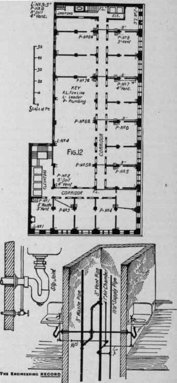
FlG.13
Continue to:
My Books

