Example Of New Method Plumbing Plans
Description
This section is from the book "Plumbing Plan and Specifications", by J. J. Cosgrove. Also available from Amazon: Plumbing plans and Inspection.
Example Of New Method Plumbing Plans
Floor Plans
An example of new method plumbing plans is given in the three following illustrations. The building illustrated, which is a hotel in Cuba, is selected because it is simple and the various points about the work can be better explained than if the work were more complicated. There are many things about the work, however, which cannot be commended, but, in order to comply with the plumbing code of Havana, or the requirements of the owner, they had to be incorporated or omitted, as the case may be. For instance, all the sewage from the entire building discharges into a fosa moura, which is a sort of septic tank, patterned after Louis Moura's Automatic Scavenger. Had this receptacle been omitted and the sewage discharged direct into the public sewer, the installation would have been simpler and better. Examining the plumbing work in detail, it will be observed that, by keeping in mind the symbols used to indicate plumbing, every part of the installation is made perfectly clear. The drainage system, it will be noted in Fig. 66, is made of cast-iron hub-and-spigot pipe, which is represented by two parallel lines, and the hubs marked at suitable intervals. Observe, also, the directness with which all the branches are run, and how they all converge toward the outlet to the main drain. Where rising stacks are to be installed, they are indicated by circles, and the size and designation of the stacks are marked. Designating stacks by letter, as A, B, C, or by numbers, will be found convenient for reference at any time, and for detailing, as will be explained later on. The locations of cleanouts are clearly indicated, as are the number and location of floor drains. Altogether, the horizontal part of the drainage system is so fully laid out that an estimator can easily scale the drawings and find out what quantity of each size of pipe will be required for this part of the work, and by counting can determine the number and kind of fittings that will be required. There is no basement or cellar below this ground floor, so that the drain pipes are buried in the earth. If located above ground, supports would be shown in their proper places. Rain leaders are not indicated on the drawings because they discharge separately on the surface of the ground or into another system of drains.
After the drainage system is marked on the plan, if the building be a large one, where a large quantity of water will be used, the sizes of the various branches and of the main drain should be calculated and marked alongside of the pipes. In ordinary cottage buildings, or other moderate sized dwellings, 3-inch stacks of soil pipe may be used, and 3-inch main drains, where rain water is excluded. If, however, the rain leaders are connected to the drainage system, the main drain should be 4-inches in diameter.
Before laying out the ground work it is, of course, necessary to locate the points where the stacks of soil and waste pipe will be installed. This will be done by finding the most out of the way places in which the stacks can be run to the various toilet or bath rooms, where at the same time they will be convenient for roughing-in the fixtures, and locating them in such places. If there is some latitude in this respect, that is, if the stack of soil pipe can be run equally well in one of several places, that location should be selected, which will permit of best arrangement of fixtures with the least expenditure of time and material. Having the rising points of the various stacks, the plumbing layout should be drawn to give the various drains the most direct runs possible. In drawing the drain pipes it should be remembered to have the hubs of the pipes on the up-grade ends of the lengths.
When the drainage system is marked on plans, there ends, usually, all effort to show the plumbing system. The water supply, which is of equal, if not greater, importance than the drainage system from an engineering standpoint, is so seldom shown that it might be stated as never being included. Indeed, it is only when plumbing plans are prepared by a sanitary engineer that the water supply systems are indicated. The object of plumbing plans, however, is to show fully what materials are to be furnished and what labor performed, and that cannot be satisfactorily done if the greater part of the work is omitted from the plans and dismissed from the specifications with the brief statement that "each fixture will be supplied with cold water or with hot and cold water, as required." To obtain satisfactory results on a big installation, not only must the system to be adopted be fully studied out and marked on drawings, but the sizes of the various pipes should be carefully calculated, so that they will be sufficiently large for their several purposes. In the present instance, the hot water must be drawn from the hot water faucet at each fixture when the faucet is opened. That necessitates a circulation pipe, and for convenience in installing the system, as well as to have the entire system controlled from a central point, manifold headers are installed and each set of risers is piped direct from the manifolds. In order that each pipe may be distinguished from the others and traced from beginning to end, the hot, cold and circulation pipes are indicated by different kinds of lines, and the key to each may be found marked on the bottom of the drawing. The service pipe can be traced from where it enters the building, through the filter, meters, and into the suction tank. From the suction tank it can be traced through the pump to the pump riser to tank on roof. In short, so fully are the water pipes marked on the plan that, by scaling them, an estimator can determine the exact amount of each size of pipe and the number and kind of fitting which will be required for the horizontal runs, and can calculate quite accurately the amount of work required to install them. Besides the drainage system and water pipes, the water filter, water meters, suction tank, pump, water heater and hot water tank are shown in their respective places on the drawing. It might be well to point out here that manifold headers would not be used under all conditions and in different types of buildings than the one under consideration. Conditions might be such that instead of separate connections to each rising line from a manifold header large mains might be run instead, and branches taken off from the mains for the different riser connections. After the runs of the various water pipes are marked on the drawing, their sizes should be calculated, regardless of the system of piping used, so they will be ample for their several purposes. At the same time the size and kind of service connection must be taken into consideration and determined upon. If the service pipe will be over 2 inches in diameter, the matter should be taken up with the water company to see if a special fitting will be inserted in the water main, or whether a multiple connection with the equivalent of water taps in the main will have to be resorted to. Having determined, the connection can be fully covered in the specifications.

Fig. 66 A New Method Ground Floor Plan

Fig. 67 New Method Upper-floor Plan
The first, second and third floor plans for this building are all similar, so that one sheet, Fig. 67, answers for the three floors. All that is indicated in this sheet, outside of the fixtures, are the location of the various soil, waste and vent stacks and the hot-water and cold-water and circulation risers. It is useless to try to indicate the layout of pipes for toilet rooms or bath rooms on the general floor plan, so the best practice to follow is the method here recommended of simply showing the arrangement of the various fixtures, and show the method of running the pipes to them on a separate detail drawing. It will be observed that no effort was made to fill in the plans completely, such as showing doors and other structural details that have no relation whatever to the plumbing work, but that simply an outline drawing was made, showing the location of the various walls and partitions, particularly those forming the rooms where plumbing fixtures are located. Between the two adjoining bath rooms it will be observed that extra wide partitions are shown, so that all the soil, waste and vent pipes can be concealed therein. There is no good reason for defacing a building by running exposed a network of plumbing pipes, or by providing boxes with removable covers for their reception. Once the drainage system, in buildings of moderate height, is made tight, if constructed of suitable materials, it will remain so and can be enclosed between the walls of a partition and plastered over. The supply pipes, however, should be exposed, or accessible. So it is that in the plan under discussion the soil, waste and vent stacks are shown concealed inside of partitions while the supply pipes are run in one of the bath rooms at the head of the tub.
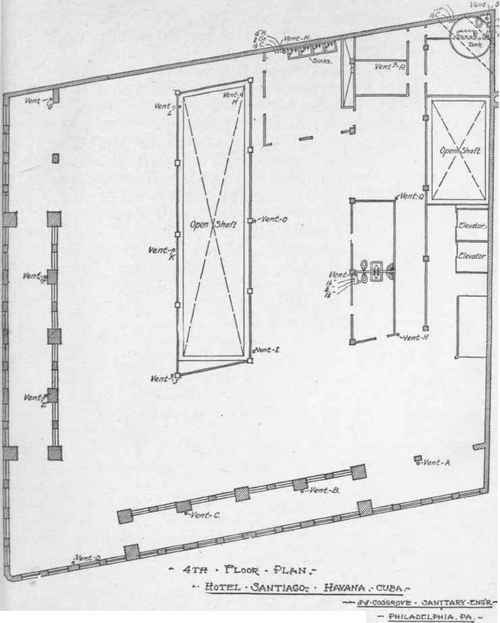
Fig. 68 New Method Roof Plan
The fourth floor of this building, Fig. 68, is partly roof garden, or open-air-dining-room. In the covered portions the location of stacks of soil, waste and vent pipes, rising lines of hot water, cold water and circulation pipes, and the kind and location of fixtures are shown. In the open part of the floor or roof the locations of vent pipes are indicated. In addition to the usual materials and fixtures shown on this plan, the house tank is shown in dotted lines in one angle of the building in the location it will occupy above the roof of that portion of the structure.


Continue to:
My Books

