Chapter XL. Hot-Water Fittings
Description
This section is from the book "Plumbing Practice", by J. Wright Clarke. Also available from Amazon: Modern plumbing practice.
Chapter XL. Hot-Water Fittings
After the boiler is properly fixed the next thing is to consider the circulation pipes. Figure 432 is a sketch diagram showing how they are fixed in some of the London jerry-built houses. The pipes are usually of 3/4-inch bore, and of the gas pipe description which is very light in substance. The bends are often carelessly made and buckled in their throats, so as to offer serious impediments to the free flow of water through them. The pipes are rarely coated inside, or galvanized, to prevent oxidation, with the result that frequently all the hot water has to be run to waste, as it is so highly coloured with iron rust. In some slightly-better houses 1-inch bore pipes are used, and in first-class work it is usual to fix 1 1/4-inch galvanized-iron or tinned-copper pipes. The iron is what is called the lap-welded steam pipe, and is very strong. The copper pipes have a lapped and brazed seam, but the last few years a great deal of patent seamless drawn copper tube has been used. Copper pipe should always be tinned when quite new and bright. When kept in stock for some time before being tinned, it is often found that the insides, which cannot be seen, do not get coated over the entire surface, patches of copper being left untinned.
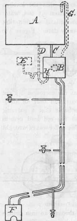
Figure 432.
Referring again to Figure 432, A is the cold-water and B the hot-water cistern. C is a pipe connecting the two. The writer has frequently met with this stupid arrangement. In some other cases the feed pipe has been connected as shown by dotted lines at D. Both of these arrangements are bad, as the hot water will sometimes work back into the cold-water cistern, rendering the contents into a heated state. This evil is more serious when the cistern, A, has to supply cold water to the sinks, etc. This can be prevented by fixing a light flap or valve on the end of the connecting pipe, as shown at H, Figure 432, but, as this valve is liable to set fast, it is not a good plan.
In some cases a small feed-cistern is fixed at the side of the hot-water cistern, as shown at E, Figure 432. This is a better arrangement, as it breaks the direct communication between the cold and hot-water cisterns, but the blunder is frequently made in fixing a 1/2-inch - in some cases a 3/8-inch - ball-valve in the feed-cistern. There is some little risk of damage to the boiler attending this arrangement. The low head of pressure on and the smallness of the ball-valve allows the water to dribble in very slowly, so that if a tap is left running, say into a bath, and another tap is opened at a level with the boiler, it is possible to empty the cistern, pipes, and boiler; and, it need scarcely be added, this is a very dangerous thing to do when the boiler fire is alight.
In some cases the draw-off taps have not been connected with the circulation pipes, but to a separate pipe fixed from the hot-water cistern. This is not to be recommended, as in the case of a high house a long length of pipe would have to be emptied of the stagnant cold water contained in it before hot water could be drawn. And again, the pipe would have to be connected to the upper part of the hot-water cistern, the lower strata of water being often quite cold. This would limit the available supply of hot water.
The writer has seen a few cases where the feed pipe was fixed direct from the cold-water cistern to the boiler. In one case the pipe was only 1/2-inch in bore, which was much too small. The feed pipe should always be so large that the cold water will run in as fast as the hot water can be drawn off.
Hot-water cisterns generally have steam-tight covers, or manholes, and have a pipe fixed from the top to the outer air above the level of the cold-water cistern. In some cases this, which is commonly called expansion pipe, is turned over the top edge of the cold-water cistern, as shown at G, Figure 432. In one case the writer saw several years ago, when the cold-water cistern was full the water covered the end of the expansion pipe, and the connection thus made created a circulation between the water in the two cisterns.
It is very important that all pipes connected to a boiler should be kept free from any stoppage, or a possibility of the water being frozen. There is no more frequent cause of boilers bursting than pipes being frozen. In some cases a patent plug, with a thin disc of copper in the centre, regulated to break when an extra pressure has been brought to bear, has been attached to the boiler. In other cases a safety-valve has been attached. Some of the safety-valves are similar to those usually attached to steam boilers. Another kind much used is called a "dead-weight safety-valve," and is shown in section at Figure 433. The top of the inner tube is conical and ground into the outer cap. Weights, A, A, A, are added in proportion to the pressure the valve has to resist, care being taken not to add more than is really necessary. This valve should always be connected with the boiler by means of a separate pipe If connected with the circulation pipes, as is sometimes done, and common keyed bibb-faucets are used for drawing off hot water, water-hammer in the pipes, caused by sudden closing of a cock, will sometimes cause the safety-valve to jump, so to speak, and allow a small quantity of water to leak out. This kind of valve is a very good one, and is preferable to some that have the weights piled on the top, making them top-heavy and more likely to leak if they should be knocked against or jarred.
It is an open question if safety-valves are to be trusted in cold countries, as it is possible the valve itself may become fixed if the water inside gets frozen.
Fusible plugs are sometimes fixed to boilers, so that if by any means - such as shortness of water or insufficient supply - they become empty when the fire is burning, the plugs will melt and thus relieve the pressure brought to bear by the sudden expansion of water into steam should it come in when the boiler is hot.
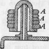
Figure 433.
In first-class houses of modern construction the old way of fixing the hot-water cisterns at the top of the house, or on an upper floor, is not so generally practised, but what is known as the cylinder system has been adopted.
Figure 434 is a sketch diagram showing one of the simplest arrangements as fixed in some of the middle-class houses. J is the boiler; K, the hot-water cylinder; L, the cold-water cistern; and M, M, M, the draw-off cocks. In this system the water circulates between the boiler and cylinder, and a pipe is fixed from the top of the cylinder and continued above the cold-water cistern. From this pipe branches and draw-offs are fixed in the various positions as necessary. The only drawback to this system is, that the water in the rising pipe being stagnant, and at times nearly cold, it has to be drawn off before hot water can be had at the cocks. In some cases a return pipe has been fixed as shown by dotted lines, and as it was only necessary for the water to circulate slowly, this return pipe has been fixed of a smaller size than the flow pipe. For best work the return should always be the same size as the flow pipe, or the circulation of the hot water is very much impeded.
In some cases the hot-water chamber has been made of iron plates rivetted to angle-irons, and made as shown in sketch, Figure 435. But even when made of 1/4-inch iron plates it has been found necessary to have several stay-rods inside to prevent the sides and top bulging out by the internal pressure. This bulging sometimes causes the joints of the pipe connections to leak, and it is nearly always the case that the manhole leaks. This manhole must, of necessity, be large enough for access for cleaning out the chamber, which is rendered more difficult by reason of the complication of stay-rods inside.
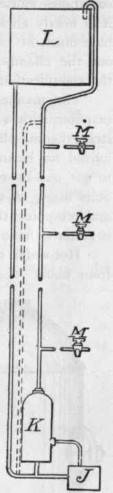
Figure 434.
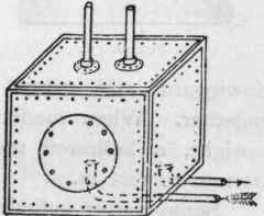
Figure 435.
The manhole plate is of wrought iron, and bolted over the manhole with a series of bolts tapped and screwed to an inside strengthening-plate. Should the manhole-plate require to be removed for cleaning-out purposes, the bolts are generally difficult to get out by reason of their having rusted in. Sometimes the bolts break off and have to be drilled out, necessitating new bolts and retapping the holes for them. It is very rarely done, but it is better to have gun-metal or copper bolts instead of the iron ones.
Hot-water cylinders are made of galvanized-iron plate, varying from about .094 to .25 of an inch, or of sheet-copper of about .035 to .120 of an inch in thickness. In some cases the copper cylinders are tinned inside.
The shape of the iron cylinders is generally as shown in sectional elevation, Figure 436. The sketch shows the position of the manholes and connecting bosses, and speaks for itself. The bottom is domed upwards, as shown, as being more convenient for rivetting, and also because if a flat bottom is put on the pressure of water is found to make the bottom bulge downwards, so that the cylinder will not stand firm on a flat shelf or platform. Copper cylinders are sometimes made with the bottom domed downwards, and, instead of being rivetted up, the seams are brazed together. When made this way, and the cylinder is to stand upright, a hollowed seating or bracket must be made for the bottom to rest in.
Some copper cylinders have the straight seams dovetailed and brazed, and the domical ends soft-soldered on, but as after a time the soldering comes away from the copper it is necessary to solder, or sweat as it is sometimes called, an outer ring of copper over the soldered seam, as an extra precaution against a leakage or breaking asunder of the domes and the body of the cylinder.
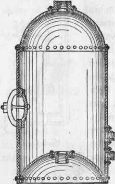
Figure 436.
Figure 437 is an elevation showing the copper cylinder as described, and with a piece broken out so as to show the section of the joints referred to.
The round cylinders are generally made with bridged manholes, as described for the boilers, for access to the inside for cleansing, etc.
Cylinders, as a rule, should stand above the level of the boiler, and should not be fixed on wooden shelves or brackets, but should have iron stands or brackets. Brick bases are sometimes built to support the cylinders, but the brackets are best, as more room is left for access for making the connections or giving any attention to them that may be necessary.
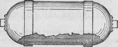
Figure 437.
Continue to:
My Books

