Chapter XVI. Drains And Traps - Continued
Description
This section is from the book "Plumbing Practice", by J. Wright Clarke. Also available from Amazon: Modern plumbing practice.
Chapter XVI. Drains And Traps - Continued
When it is necessary to have one drain branched into another it is important to have a Y junction pipe, as in Figures 136 and 137, instead of using a square or right-angled one, as in Figure 138. The reasons were fully given when illustrating soil-pipe branches. In the case of drains with horizontal square branches, when sewage is discharged down a branch, as much flows back up the main drain as in the direction of the current, with the result that the liquid portion afterward dribbles away, leaving all solid or semi-solid matter behind. This will lie in the bottom of the pipes until a flush from a higher level of the main drain removes it.
Where a drain lies flat, or has only a slight fall, any sewage flowing down very frequently eddies, and runs a short distance up any branches, especially when they and the mains are of the same size. It would entail a certain amount of expense to have branches especially made so as to offer resistance to this, but the evil can be avoided by raising the branch a little, as shown in section, Figure 139. Where a small pipe discharges into a large one this evil will not happen, unless the main drain is running so full that sewage reaches up to the branches.
Figure 140 represents a branch drain that was continually stopping up, and, having to be frequently forced, it was decided to open it until the cause was found. This proved to be at its junction with the main drain. Figures 140 and 141 are section and plan illustrating the cause of it all. The main drain was 12 inches and the branch 4 inches in diameter. The 4-inch drain was from a soil pipe, with four water-closets upon it. In the bottom of the 12-inch pipe was a pyramid formed of wet paper, and every time a water-closet was used, the wet paper, falling vertically on the bottom of the pipe, as shown, gradually accumulated until it eventually choked the end of the 4-inch pipe. If any reader were to take a handful of wet paper and let it fall from a height, and then two or three more, one after the other, on the top, and then try to push it over, he would be surprised to find the resistance it would offer. In the above case there was very rarely any water passed down from the upper portion of the main drain - in fact, only when rain was falling.
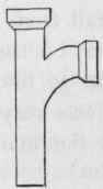
Figure 136.
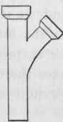
Figure 137.
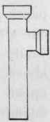
Figure 138.
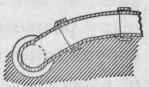
Figure 139.
Most of the best sanitary engineers have inspection-chambers, or manholes, built at all junctions of drains, and also at any change of direction, and have only a half-pipe or half-bend at that point, so that if any obstruction should lodge there it can easily be removed; or, if the obstruction should be in the straight lengths, any ordinary drain-machine (which is similar to a chimneysweep's) can be pushed through, and so clear it away. A great many people dub themselves "sanitary engineers," and, by dint of copying others, sometimes make a fairly good job, but, for want of experience, very often make serious mistakes. The writer saw a manhole, arranged as shown at Figure 142, and the drains being used. The branch drain from the water-closet was joined to the channel pipe in such a way that the sewage was discharged up the main drain, and then had to flow back again to pass into the sewer. Excreta lay at A until a current passed by from the upper part of the drain to wash it away. Another and very common mistake of some of these so-called sanitary engineers is to bring a junction in at right angles in a manhole, and also to have the bottom channel too shallow, so that anything coming down the branch washes up and lies on the side ledges formed for a man to stand upon when examining or clearing a drain. Figure 143 is a section showing this, and at B the writer has sometimes seen as much semi-solid sewage as would nearly fill a bucket. Even in some cases where these manholes have been fairly well arranged, want of thought, and, in some cases, an ignorance of hydraulics, has led to another error, which is shown in Figure 144, Figure 145 being a section on A, B. It must not be supposed that because the branch channel is curved that the water will follow it. As a matter of fact, it will wash up, and sometimes leave a deposit at C. To overcome this difficulty it is necessary to curve this bent channel, as shown in section at Figure 146. The dotted lines show the surface of the water as it passes around the bent portion. It is not necessary to raise the side, D, so high as the other, but if it is not done the manhole does not present a smart appearance when finished.
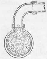
Figure 140.
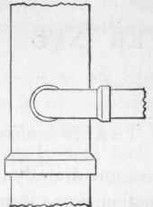
Figure 141.
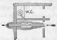
Figure 142.
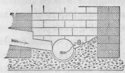
Figure 143.
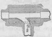
Figure 144.

Figure 145.
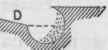
Figure 146.
Most manholes have half-pipes fixed for the sewage to pass through, and these channels have the sides built up with brickwork. There is no reason why a proper channel pipe, with junctions, should not be made all in one piece, as in sketch, Figure 147; or bends, as in Figure 148, which could be fixed quite easily, and thus avoid the patchy appearance these places generally present as now done. In some cases it would be necessary to have channel branches instead of pipes, as shown in Figure 147. Before leaving the question of manhole junctions, it would be as well to draw attention to another important point, and that is, not to allow two branches on opposite sides to be directly facing each other, in which case water or sewage coming down one pipe, with any velocity, would rush up the one opposite. Figure 149 shows this evil, and Figure 150 the precautions to be taken to avoid it. Ordinary manholes are built with common bricks, and where of considerable depth, strong wrought-iron loops are built in the angles, as shown at X, Y, Figure 150, so that a man can get down without the aid of a ladder, which would occupy space, and leave little room for him to work in. Sometimes these manholes have a coating of lime-wash, which makes them look clean and smart. Some sanitarians will have them rendered in cement and sand, worked up to a face.
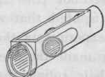
Figure 147.
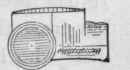
Figure .148.
Continue to:
My Books

