Chapter XXVIII. Wash-Hand Basins. Part 2
Description
This section is from the book "Plumbing Practice", by J. Wright Clarke. Also available from Amazon: Modern plumbing practice.
Chapter XXVIII. Wash-Hand Basins. Part 2
Referring again to plug-wastes, Figure 285 represents, in section, the ordinary style of making them, and at H is shown how the water-way may be contracted by allowing the lining of the union to enter the washer. Sometimes this lining is butted up to the washer, and a leatner grummet placed between. When screwing up the union this grummet will get out of its position, or perhaps get squeezed so that it projects inside, as shown at J, in section, Figure 286. By making the brasswork as shown at Figure 287, the water-way can be made of equal diameter throughout, and if the lining is ground into the washer, as shown at K, similar to steam-unions, no packing or grummet is required. To get a shoulder on the lining to fit the cap, the substance of the metal in the brass washer must be a little thicker, as shown at L, than in the other examples given. The flange of the washer should be as large as the sinking in the basin to avoid a space, which always looks dirty. Some makers fix a small brass grating, as shown by dotted lines, M, Figure 286, to prevent finger-rings or small pieces of soap and other matters from getting into the waste pipe, thus adding to the evils of the already too much contracted water-way. It is much better to drill holes and fix brass cross-bars, as shown by dotted lines at N, Figure 287. These wires need not be very thick, as little or no strength is required, but as they contract the water-way, the brasswork can be turned out slightly larger, as shown in section, to allow for this. When large washers and plugs are used for wash-hand basins, it is advisable to make the plugs of vulcanized india-rubber, as described when writing on baths, as it sometimes happens that a large brass plug will break the basin when allowed to fall into it. Plugs have been objected to, as they require chains to prevent their being lost. The links of the chains get filled up with soapy matter, so that they always look dirty and smell unpleasantly. In addition, when the plug is made too slender in the tapering, it sometimes fits into the washer so tightly that the chain is broken in the attempt to pull it out. Or, perhaps, the plug when cold is placed in the washer when hot. On cooling, the plug will sometimes fit so tightly as to resist all efforts to pull it out, so that the union has to be uncoupled and the plug knocked out from the under side. This only applies to metal plugs.
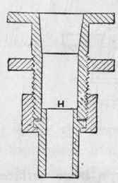
Figure 285.
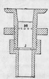
Figure 286.
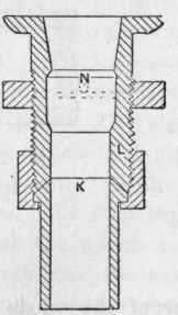
Figure 287.
Figure 288 represents a brass plug and washer used by a firm of sanitary engineers. The plug has an indiarubber ring sprung on and a spindle, with a nut on the bottom end, working through a guide-bar. A projecting slip is cast on the spindle, and a corresponding slot in the guide-bar, so that a slight turn given to the plug, when open, will cause it to remain. The knob, O, for lifting the plug, should be flush with the bottom of the basin, to prevent injury to the user's finger-nails, and also to prevent the user unintentionally lifting it so as to empty the basin. If the plug is made a good size, the spindle should be short, so that it cannot be opened too wide, so as to allow anything to fall down the waste pipe. When these plugs are fixed to wash-hand basins each user should discharge his own water, as it is unpleasant for the next comer to have to put his hand into the dirty water to reach the plug to open it.
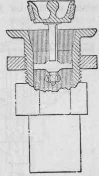
Figure 288.
One maker of sanitary fittings has a "trigger" connection to lift a plug of the kind last described. Figure 289 is a sketch showing the arrangement. P is the trigger, R is an indiarubber joint. The trigger is placed on the front side of the basin, so that the user has only to press his hand on it to open the plug In some cases the trigger is placed at the side of the basin, and a spindle continued through the slate or marble top, and a metal, porcelain, or other kind of knob fixed for pressing down the trigger. This is shown by dotted lines.
Several makers have "valves" for discharging the water out of the basin. Some of these valves are similar to those described when writing on baths. Figure 290 represents one made by plumbers out of lead pipe. The part S is made of brass, T is a flanged connection, and U is a slip-joint in the pipe which forms the overflow. Ears are soldered on for screwing to the back boards or wall for fixing. When making these quick waste-valves the plumber sometimes makes the valve pipe too long, so that the branch waste pipe from the basin is some 2 or 3 inches above the flanged connection containing the valve. In this case the valve is an obstruction to the free escape of the water. The branch pipe should be as near the valve as possible, so that, when lifted, the valve will be above the branch waste, as shown by dotted lines at V, and thus allow the water a free passage. When properly made, this waste fitting will enable a good sized basin to be emptied in three or four seconds; but when badly made, it takes five or six times as long to discharge the contents of the bowl. Very strong wire should be used for connecting the valve to the pull-up knob. If thin wire is used it sometimes stretches by constant usage until it becomes so long as to only partly open the valve. Another reason for paying especial attention to the thickness of the wire is because the whole of the apparatus has to be taken down for access to repair a broken wire, and it is very troublesome to get it the exact length. If too short, the valve would not fit tight in its seating, and if too long, the valve would only partly open. When this waste apparatus is used, it is not necessary to have an overflow-arm to the basin, but when an overflow-arm is used the pipe, U, can be omitted.
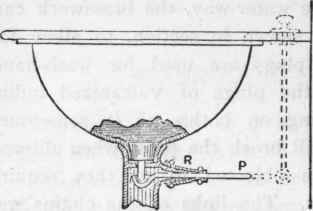
Figure 289.
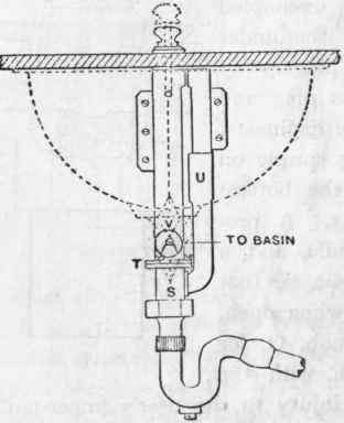
Figure 290.
Continue to:
My Books

