Iron Drains - Continued. Continued
Description
This section is from the book "Plumbing Practice", by J. Wright Clarke. Also available from Amazon: Modern plumbing practice.
Iron Drains - Continued. Continued
It is always best to make provision for removing obstructions in iron drains when they are first laid, so as to avoid the necessity of disturbing them afterward. If they are laid in perfectly straight lines, with an access-chamber built over each bed or junction, or at the extremities of the drains, channel, or half-pipes could be used at those points, as described when speaking of traps and manholes; but as these places necessitate air-tight flap covers over them, and are sometimes very near the surface, it is an advantage to have fittings specially made, with an access or movable cover. Some makers have an extra socket cast on, in which a brass screw-cap can be bedded, but, no matter how well done, this always looks patchy, and, if hot and cold water is discharged through the pipes, it is open to the objection that the various metals used would expand and contract unequally, so that after a time they may become not air-tight. Again, these screw-caps are not large enough for removing some of the objects which find their way into the drains, nor for a man to pass his arm through to grasp them. These kind of places should be large enough for this, and also to pass drain-rods through to force any obstacle which is out of reach through and clear of the drains, and so shaped that the drain-rods could be sent up as well as down the drain from the same inspection hole. The shape of the hole should be similar to that described above as being drilled out, and should be cast at the same time as the pipe, with a flat flange around the hole if the pipe is to lie horizontal, on which could be bolted a flat cast-iron plate. If this cover is for an upright pipe a piece should be cast on the back side to fit into the opening, so that the inside of the pipe shall be perfectly cylindrical, as shown at Figure 174.
Makers of iron pipes and other fittings supply junctions cast from the same moulds as those used for water-mains. Now, water-mains can be laid perfectly level, or even up hill, but drains must always fall in the direction of the current that passes through them. Square junctions for iron pipes are made as in Figure 175. What are known as branches are made as in Figure 176, and have a spigot-end at A instead of a socket, and no doubt that is why Figure 175 is used. This is all right for water-mains, but if they are used for drain-work the result will be that all the joints on the branch will be made imperfect, as the lead will have to flow upward to entirely fill the socket. The reader is referred to Figure 177, which illustrates what would occur under these circumstances. On looking at this, which is drawn in section, it will be seen that the joint is not solid, as there is no way of escape for the pent-up air at B, whereas, if the inclination of the pipe had been the other way, the air would be displaced as the lead was poured in. This would occur at every joint in the branch drain. It could be overcome by using a double socket or collar, and making the joint on the branch before laying it in position. Figure 178 is a section of the ordinary kind of collar used for connecting two spigot-ends of pipes, and it need scarcely be added that two lead joints are required to be made to it. A good job can be made in this way, but it is much better to have a socket cast on the branch, and so avoid the extra labour, lead, etc.
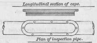
Figure 174.
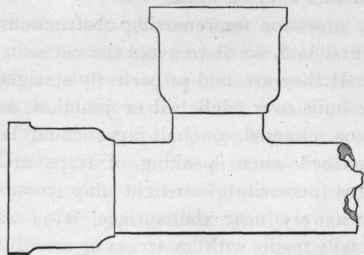
Figure 175.
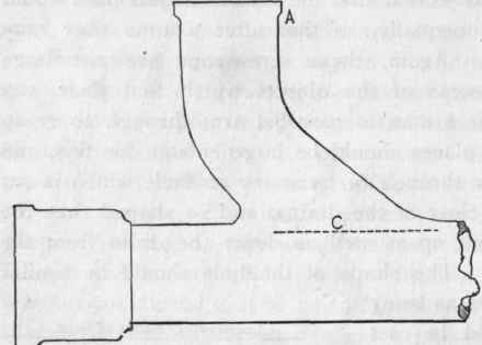
Figure 176.
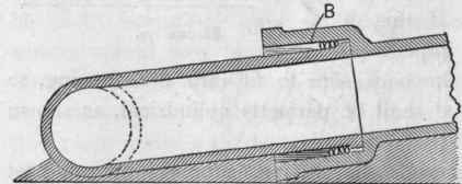
Figure 177.
The ordinary warehouses keep only those which are made for water-mains, but will always make castings to the purchaser's order and directions.
Where the end of a drain turns upward to receive the end of a stack of pipe, it is a good plan to fix what is commonly called a "duck's foot" bend. This is a bend with a foot cast with it, as shown at Figure 179, and which helps to support the weight of the vertical pipe.
A bed of concrete should be made for this to stand upon; indeed too much care cannot be taken to avoid settlement of any part of the drain. It is almost an every-day experience to find the end of the soil pipe not made good to the drain. This no doubt has arisen in a great many cases when - the walls of the building having good foundations and the soil pipes being firmly fixed - the earth containing the drain has subsided and the joints have become broken. At the risk of being thought wearisome I must repeat that concrete foundations for drains, under almost all conditions, are of the utmost importance. For want of concrete, a drain was found to have subsided and become so defective that it had to be taken out, and the earth beneath was found so charged with sewage that it had to be dug out to a depth of five feet before it could be considered to be free from offensive matter. This was a private residence, in which eleven children and two servants had all been ill This and other experiences also prove that the drains cannot be too carefully laid, etc, and that they should be of the very best materials. If properly done the first cost would be the last cost, and would be much cheaper in the end, although some think the cost excessive if they have iron drains rather than others which are considered cheaper. These latter entail a permanent tax on the householder for repairs or renewals, to which may be added the annoyance and inconvenience of continually having the house upset by workmen. There is one little matter in connection with junctions for iron drains that should not be lost sight of. They should always be inspected inside, at the point of junction, as it not infrequently happens that where the cores meet a serrated ridge of iron is left, around which passing objects can cling. The position of this ridge is shown by dotted lines at C, Figure 176. This (in some cases they are only little spurs) can be knocked off with a long chisel and hammer without doing any injury to the fitting.
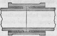
Figure 178.
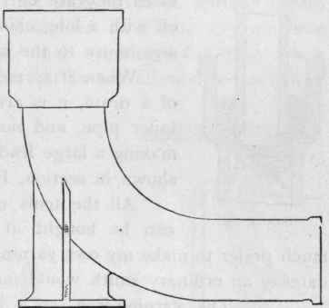
Figure 179.
When it is required to reduce the diameter of a drain, it is always advisable to use a proper taper pipe, and not to attempt to get over it by making a large lead joint, in the same manner as shown in section, Figure 180.
All the tools necessary for iron pipe laying can be bought at the usual tool shops, but I much prefer to make my own yarning and staving-irons, although I daresay an ordinary smith would make them in one-half the time. The yarning-iron, as it is called, is generally made of steel, but I think a good tough piece of iron is better. As it is not necessary to use a hammer with this tool, I like the handle-part rather heavy, so that it does not jar the wrist so much when working the yarn tight home, and if it is slightly roughed it does not make the fingers ache so much by gripping the tool. A good set should be given to this tool, so that the fingers do not get pinched between it and the pipe. It is not at all uncommon to have the skin chafed off the little finger by rubbing against the pipe when yarning. Figure 181 is an illustration of this tool. The staving, calking, or setting-up tools should be made of steel, tempered rather soft. Octagonal-sectioned steel is best, as it is better for holding. The hands, after using the clay, get so smooth inside that it makes them ache when having to grip anything smooth. These tools should be as short as convenient, so that when working in a trench they would leave more room for swinging the hammer than if the tools were longer. Another reason is, that with short tools the hands do not get hit so often with the hammer, especially when setting up the under side of the joint. When doing this, the man generally stands astride the pipe, the tool in one hand passed round one side of the pipe, and the hammer in the other passed round the other side, so that he cannot see what he is doing to the under side of the joint, but a good pipelayer can tell by the touch if it is properly made. For trenchwork these tools should be made with a set, as Figure 182, but for pipes fixed in upright chases in walls they should be rather straighter, as Figure 183, as there is generally objection to having much brickwork cut away for a joint hole. In some cases, where it is not allowed to cut away for access for setting up a joint, it is necessary to have specially-made tools. Figure 184 I have used under these circumstances, but a pair of them is required when it is necessary to work from both right and left hands. Figure 185 is another tool I had to have especially made for setting up a joint beneath a stone landing, and which could not be done any other way, X being the part struck with the hammer. The hammer used for jointing has usually a short club head and a short handle, the blows given with it being short and quick. The hammer should be held lightly; if firmly grasped it makes the fingers ache by long usage, and at the same time the constant jarring causes a pain in the wrist, and, moreover, the hammer falls with more force if not grasped too tightly, as in the act of striking the face adjusts itself to the head of the tool better.
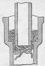
Figure 180.
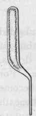
Figure 181.
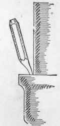
Figure 182.
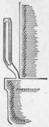
Figure 183.
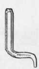
Figure 184.
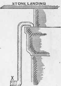
Figure 185.
Continue to:
My Books

