Laying Out The Keel
Description
This section is from the "The Elements Of Wood Ship Construction" book, by W. H. Curtis. Also see Amazon: The Elements Of Wood Ship Construction.
Laying Out The Keel
The first step in laying out the keel is to locate and scribe across the top and down each side all frame centers on each piece of the keel, as shown on the plans. These are then numbered in the same order as marked on the plans. This is very important, as nearly all construction details in ships are located by frame numbers. The frame center-lines should be scribed with a race knife, and the numbers marked with heavy blue or black crayon.
The plans show the location of the scarfs, and these may now be accurately marked out between the proper frames. The nibs of scarfs, unless otherwise called for, should land about half way between frame centers. If a scarf six depths long is too short to land thus, it should be made longer, not shorter. The length of scarf to be used is generally indicated on the plans.
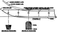
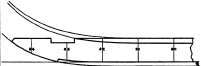
Figure 8.
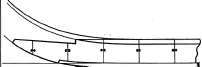
Figure 9.
Keel Ends.
Keel - Proper Placing Of Scarfs In Three Piece Keel.
Figure 12. Layout Of Spring On Keel.
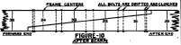
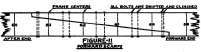
Keel scarfs must be clinch bolted. A common rule is two bolts between each frame. The plans should be carefully noted in this respect, as additional bolts are sometimes called for. These bolts, in so far as possible, should he kept clear of the frame landings and arranged as shown in Figs. 10 and 11.
The forward and middle scarfs are generally set as shown in Fig. 11. Sometimes the after scarf is reversed, as shown in Fig. 10. This permits the removal of the after piece of keel in case of damage without rescarfing the piece next to it. Where this is not done all scarfs will set as shown in Fig. 11.
Molds are furnished from the loft for the forward and after ends of the keel. These molds have the frame numbers scribed on them, and when matched up with the same frame numbers on the keel give the exact location of the cuts.
Three styles of forward ends are shown in Figs. 7, 8 and 9. These may be named in very much the same manner as scarfs. Fig. 7 would be called "plain," Fig. 8, "locked," and Fig. 9, "nibbed." The depth of nib or lock may be the same as that of nibs for scarfs, but in no case should it be less. Where the lock or nib is used, the rabbet lines are so adjusted in the loft that the outer rabbet line will cross well up on the lock, or nib, but not higher than the top of the keel. The use of the lock or nib properly arranged avoids the forming of a shim where the outer rabbet line leaves the keel. In the plain end, where this shim is always formed, some difficulty is often encountered by the shim starting to split out when the rabbet seam is calked.
The after end of the keel must be worked to receive the lower ends of the stern, or propeller post, and the rudder post, if one is to be fitted. These landings are very often called "steps".
If the vessel is a single-screw ship with a wood rudder, it will have a propeller post and a rudder post. The propeller post is also the stern post. See Figs. 13 and 15. A single-screw ship with & steel rudder will have propeller post, which is also the stern post. See Fig. 16. A twin-screw ship, with a wood rudder, will have a stern post, which is also the rudder post, and will have no propeller post. See Fig. 14.
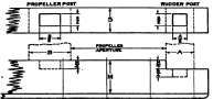
Figure 13. For Single Ships with wood Rudders.
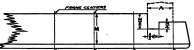
Figure 14. For Twinships with wood rudders.
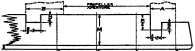
Figure 15. For Single screw with wood rudders.
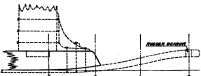
Figure 16. For Single or twin screw with steel rudders.
After Keel Ends.
Fig. 13 shows the boxed, or blind, mortise step for stern and rudder posts. Figs. 14 and 15 show the open mortise step. Either of these steps may be used with any arrangement of posts. If a mold is not furnished for locating and marking out the steps, then the distance from a given frame center and the dimensions for the mortises are supplied from the loft, or drafting room. The proportions of mortise and step may or may not be indicated on the plans. Very often this is left to the judgment of the carpenter foreman. Good proportions are shown in Figs. 13, 14 and 15.
Fig. 16 shows an arrangement where a steel rudder is fitted. It will be noted that a steel shoe is used to carry the lower rudder bearing, and that the keel is extended abaft the post only far enough to receive a steel knee. In addition, there are steel side plates (not shown) extending from the shoe well up on each side of the stern post. All of the types shown are fitted with steel or bronze side plates extending along each side of the keel and well up on the stern and rudder posts. These will be more fully described later on.
The rabbet on the keel is laid out from offsets taken from the loft floor. The offsets give the distances in from the side for the inner rabbet line and down from the top for the outer rabbet line. Unless there is a back rabbet the surface between the two lines is cut straight. The offsets are taken at designated frame centers. Where there is a back rabbet, fids, or small molds, are prepared in the loft to fit the shape of the rabbet at about every other frame center. The inner and outer rabbet lines are then used as limit guides for the fids.
The rabbets at the extreme ends of the keel should not be cut until after the framing has been completed. Then, as the frames are dubbed, the rabbets are cut and faired.
As before mentioned, keels are laid without the shoe when the main keelson bolts are to be clinched under the keel. After the main keelsons are in place and fastened down, the keel is jacked up a section at a time and the shoe slipped into place in short pieces. Since the shoe is merely a fender for the keel it need not be in long lengths. It is fastened with common ship spikes, spaced about 12 inches apart and staggered.
After the keel has been laid on the blocks and the scarfs bolted up it must then be faired to the spring points. This is best done by means of an instrument called a transit, although it can be, and very often is, done by sighting with the eye. After fairing to the spring the keel must then be shored sideways until perfectly straight. If there is a taper in siding at each end, a full length centerline is scribed for this purpose. While a straight-sided keel can be sighted fairly well with the eye, a tapered keel should always be lined with a transit.
The proportions for spring points between the middle and the ends of the keel are shown in Fig. 12. The figure has, of course, been very much foreshortened to bring it within the limits of the page, but this does not alter the principle involved.
In the figure, S represents the amount of spring, and L the length of the keel.
Example
Let S equal 5 inches and L equal 240 feet. Then L over 8 equals 30 feet; 1/16 of S equals 5/16 of one inch, 4/16 of S equals 1¬ inches, and 9/16 of S equals 2 13/16 inches. Therefore, the keel at a point 30 feet each way from the middle and lowest point will rise 5/16 of one inch from the line N-N; 60 feet out from the middle it will rise 1¬ inches above the line N-N; 90 feet out, 2 13/16 inches, and 120 feet out 5 inches, or the full amount of the spring. Obviously, these offsets may be subtracted from 5 inches and the remainders measured down from the line 0-0 passing through the ends of the keel, and in practice this is the simpler way to do it.
Continue to:
My Books

