Part IV. Gear Cutting
Description
This section is from the book "Machine Shop Work", by Frederick W. Turner, Oscar E. Perrigo, Howard P. Fairfield. Also available from Amazon: Machine shop work.
Part IV. Gear Cutting
Theory of Toothed Gearing. The fundamental principle of toothed gearing is that of two cylinders or portions of cones with their surfaces in contact, and rolling together in opposite directions.
The first condition, that of cylinders, is shown in Fig. 258, representing the two cylinders A and B, the axes of both being in the same plane and parallel, and the periphery of the cylinders in contact. It is evident that if the cylinder A be rotated in the direction of the arrow, the frictional contact will cause the cylinder B to rotate in the opposite direction.
The second condition, that of cones, is shown in Fig. 259, representing the two cones A and B, the axes of both being in the same plane, but at right angles to each other, and the outer surfaces of the cones in contact. The action is the same as that of Fig. 258.
It will also be evident that if the cylinders in Fig. 258 are of equal diameters, and consequently of equal circumferences, the rotation of A through a complete revolution will produce a complete revolution of B. If A is one-half the diameter of B, the latter will make but half a revolution to one complete revolution of A; while, if the cylinder B is one-half the diameter of A, it will make two complete revolutions to one of the cylinder A.
This proposition provides for no slipping of the cylinders on each other. For the purpose of transmitting power, the faces of these cylinders are provided with teeth, which are cut parallel to the axes of the cylinder; the teeth of each cylinder interlock with those of the other and effectually prevent any slipping. By this means we produce a pair of spur gears. In the case of the two cones, or a suitable portion of them, if the teeth are formed radiating from the apex of the cone, they become a pair of bevel gears.

Fig. 25S. Two Cylinders in Contact.

Fig. 259. Two Cones in Contact.
The simplest form and the one in most common use, is the spur gear. All other forms are but modifications of it in one way or another, the general principle and the principle upon which the teeth are formed being practically the same in every form of gear in use.
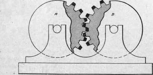
Fig. 260. Tooth Gears in Contact.
It therefore becomes necessary to study carefully the essential features of the spur gear, and to understand thoroughly its construction.
It being one of the conditions of the problem that the surfaces of the cylinders shall remain in contact, as shown in Fig. 258, teeth must not be formed in their surfaces by cutting grooves in them, for the reason that, to cause the teeth to interlock, it would be necessary to move their axes closer together, thus overlapping the original surfaces. Teeth cannot be added to the cylinders as this would necessitate moving the cylinders farther apart, thus separating the contact surfaces.
This being the case, the teeth must be formed by a combination of both the above methods, cutting the grooves one-half the depth of the proposed teeth, and adding between the spaces thus formed an equal amount to complete the partially formed teeth. They will then present the forms shown in Fig. 260, the added portions being distinguished by being drawn solid instead of being sectioned. They are called the addendum.
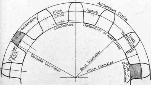
Fig. 2G1. Names of Tooth Parts.
The teeth now interlock properly by falling into the spaces, the original surfaces of the cylinders remaining on the contact line; and the diameters of these cylinders still give the base circles for all calculations as to speed, numbers, and dimensions of teeth and similar purposes. These circles are called the pitch circles. When a pair of gears vary in diameter by a ratio of 1 to 3, or more, the larger is called the wheel, and the smaller the pinion.
Names of the Tooth Parts. The names of the tooth parts are given in the diagram, Fig. 261, in order that the student may become perfectly familiar with the technical terms used in describing or referring to the teeth of gears, and the methods of calculating, designing, and drawing their various parts.
The pitch diameter is the diameter of the pitch circle.
The addendum circle has the same diameter as the outside diameter-that is, the diameter over the points of the teeth.
The dedendum circle, or root circle, is the circle at the bottom of the teeth.
The pitch is the distance from center to center of the teeth when measured on the pitch circle. When thus measured, it is called the circular pitch.
The face of the tooth is that portion of the curve outside of the pitch circle.
The flank of the tooth is that portion of the curve within the pitch circle. *
The thickness of the tooth is its width, taken as the chord of an arc of the pitch circle.
The space is the distance between adjacent teeth, measured as the chord of an arc of the pitch circle.
Continue to:
My Books

