Designing Gears
Description
This section is from the book "Machine Shop Work", by Frederick W. Turner, Oscar E. Perrigo, Howard P. Fairfield. Also available from Amazon: Machine shop work.
Designing Gears
Fixed Pitch Method
Formerly the teeth of gears were designed on the basis of a fixed distance representing the pitch. This was usually based on the common fractions of an inch or multiples of them, as 1/4,3/8,1/2,5/8,3/4,7/8,1, 1 1/4,1 1/2,1 3/4, 2, 2 1/2, 3 inches, etc. The desired number of teeth multiplied by the given pitch gave the circumference; and the distance thus found divided by 3.1416 gave the diameter of the pitch circle.
The pitch was divided into 15 parts, 7 of which represented the thickness of the teeth and 8 the width of the space. To find the length of the teeth, the pitch was divided into 10 parts, of which seven represented the length of the teeth-3 parts being that portion outside of the pitch circle and 4 parts the length inside of it, 1 part being allowed for bottom clearance. Such a method involved many tedious calculations, and in due time mechanical engineers devised a method simpler and more convenient, which has of late years been exclusively used for this purpose.
Diametral Pitch Method, By this system the pitch is design nated by a number instead of giving the length of the pitch in inches*,
This number indicates the number of teeth for each inch of diameter of the pitch circle. Therefore, if the diametral pitch is 6, and the diameter of the pitch circle is 10 inches, the gear will have 6X10, or 60 teeth. Thus we know that if the pitch is 6, or, as usually expressed, "6 pitch", and the gear has 60 teeth, the pitch diameter is 60÷6, or 10 inches. And if the gear has 60 teeth, and the diameter of the pitch circle is 10 inches, the pitch is 60÷10, or 6 pitch. We have then the three following simple rules:
(1) Multiply the diameter of the pitch circle by the diametral pitch to get the number of teeth.
(2) Divide the number of teeth by the diameter of the pitch circle to get the diametral pitch.
(3) Divide the number of teeth by the diametral pitch to get the diameter of the pitch circle.
The proportions of tooth parts are determined by methods quite as simple as the question of pitch. They are as follows:
The addendum is equal to one inch divided by the diametral pitch; hence that on a 6-pitch gear will be 1/6 of an inch.
The dedendum is a like distance increased by the clearance, which is equal to one-tenth of the thickness of the tooth on the pitch circle.
The thickness of the tooth, and the width of the space at the pitch line, are not determined by a rule similar to that given in the former method. In accurately cut gears, the width of the space exceeds the thickness of the tooth by only as much as may be necessary to permit the gear teeth to roll freely together, and need not be over .03 of the circular pitch. In cut gears for ordinary purposes, this amount may be doubled; while in gears having cast teeth, it may need to be as great as 0.10 of the circular pitch depending, of course, upon the accuracy of the casting.
In order to afford a correct impression of the relative dimensions of spur-gear teeth of different diametral pitches, Fig. 262 is given, in which the gear teeth are shown full size. These are the more common pitches. Those larger than here shown are usually 1, 1 1/2, 2, 2 1/2, and 3 pitch.
Development of Qear-Tooth Curves. Epicycloidal Curve. This is a matter of considerable importance, and should be thoroughly understood in connection with the work of gear cutting:.
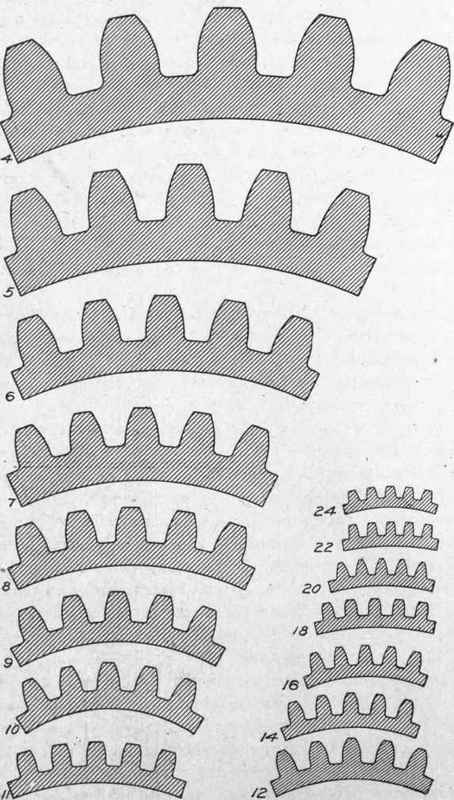
Fig. 262. Proportions of Teeth of Different Diametral Pitches.
Formerly the epicycloidal curve was considered to be the most appropriate, since it is traced by a fixed point in the periphery of one cylinder rolling upon another. This is a perfectly correct theory, and many excellent gears are still made with this form of teeth.
There is one serious disadvantage, however, in gears with teeth so formed. In gears of much variation in diameter the teeth are so different from each other in form that they will not run properly with other gears varying much in diameter from the particular gear designed to run with them. The result was a great variety of curves in gears with cast teeth, and of cutters, when the teeth were cut from solid blanks, which often proved very troublesome and expensive; and many efforts were made to produce some more satisfactory method.
Involute Curve
The involute curve was experimented with, and satisfactory results were obtained. It possesses several advantages over the epicycloidal curve, which may be stated as follows:
A single curve is sufficient, while in the epicycloid a compound curve was necessary.
Undercutting the flanks of the teeth is not necessary.
Gears of any number of teeth will run properly with other gears of any number of teeth indiscriminately. This is a very great advantage in many respects.
Cutters properly formed to cut involute teeth may be used for gears of a considerable variation as to numbers of teeth. This fact greatly reduces the number of cutters of each pitch that are required or cutting a complete range of work from pinions of 12 teeth to a rack. Where 8 cutters are required, the ranges of work are as follows:
No. | 1 | will | cut | from | 135 | teeth to a rack | |||
No. | 2 | will | cut | from | 55 | teeth | to | 134 | teeth |
No. | 3 | will | cut | from | 35 | teeth | to | 54 | teeth |
No. | 4 | will | cut | from | 26 | teeth | to | 34 | teeth |
No. | 5 | will | cut | from | 21 | teeth | to | 25 | teeth |
No. | 6 | will | cut | from | 17 | teeth | to | 20 | teeth |
No. | 7 | will | cut | from | 14 | teeth | to | 16 | teeth |
No. | 8 | will | cut | from | 12 | teeth | to | 15 | teeth |
The involute curve is generated mechanically by a point at the nd of a cord which is unwound from the surface of a circular disc or a cylinder. The curve is generated as shown in Fig. 263. A is an arc representing the cylinder, with its center at B. From the vertical line BC, and on the arc A, are spaced at equal distances the points 1,2,8, 4, 5, 6, 7,8. Radial lines are drawn from each of those to the center B. From each of these points are drawn the lines a, b, c, d, e, f, g, which are tangent to the arc A. From 2 as a center, and with the distance 1-2, the portion of the required curve from the arc to the line a is traced. From 8 as a center, with the distance 1-8, the portion of the curve from a to b is traced. And so on, until the involute curve D is traced as far as may be necessary.
In the practical use of the involute curve thus determined, an arc of such radius, and with its center so located as to approach closely the true curve, is generally used, and forms not only the face but the flank of the tooth. For this purpose, gears are classified according to the number of teeth as follows:
First Class- all gears having over 30 teeth
Second Class-all gears having 19 to 29 teeth, inclusive
Third Class- all gears having 12 to 18 teeth, inclusive
Continue to:
My Books

