Spiral Gears
Description
This section is from the book "Machine Shop Work", by Frederick W. Turner, Oscar E. Perrigo, Howard P. Fairfield. Also available from Amazon: Machine shop work.
Spiral Gears
As has heretofore been stated, the spur gear has its teeth cut in a line parallel to the axis. If the teeth are cut at an angle to the axis, and the cut continued by the gradual rotation of the gear blank as it advances, a spiral gear will be produced. If the cut is prolonged, it will finally make a complete revolution and arrive at the original line parallel to the axis of rotation. The lead of the spiral is the distance from the beginning of the cut to a point where the revolution is completed. The angle of the spiral is found in a manner similar to that described for the diagram, Fig. 274. As applied to this case, the rule will be: divide the number of inches of the circumference of the cylinder on which the spiral is to be cut by the number of inches in the lead, and the quotient will be the tangent of the angle of the spiral, the angle being found from a table of natural tangents. Thus we have the following rule: Divide the circumference by the tangent of the angle to produce the lead; or multiply the tangent by the lead to produce the circumference.

Fig. 274. Diagram for Finding Angle of Worm Thread.
In making calculations for spiral gears, the pitch diameter, and not the outside diameter, is understood. Spiral gears have several properties that should be remembered in making calculations for them. It is assumed in each case that the gears are engaged, or in mesh, with one another.
(1) Two spiral gears of equal diameter, number of teeth, and angle of teeth, will have the same lead of spiral.
(2) If two spiral gears are of equal diameter, one having twice as many teeth as the other, one will have twice the length of lead of the other.
(3) If two spiral gears are of equal diameter, one having twice as many teeth as the other, the teeth of one will have twice the angle of the other.
(4) Two spiral gears of equal diameter, on parallel shafts, will have the same angle of teeth on both.
(5) Two right-hand spiral gears must have the angles of their shafts at an angle equal to the sum of the angles of the teeth of both gears.
(6) One right-hand and one left-hand spiral gear must have the angles of their shafts equal to the angle of the teeth of one gear, less the angle of the teeth of the other.
(7) If two spiral gears are of equal diameter, one with twice as many teeth as the other, the gear with the lesser number of teeth will have them at twice the angle of the other.
(8) If one of two spiral gears has teeth at an angle of 45 degrees the other having twice the number of teeth, its lead will be twice as great and its pitch diameter twice that of the other.
(9) Diameters being equal, double the number of teeth indicates one-half the angle and vice versa.
(10) If the angles of teeth are equal, either gear may be the driver. If the tooth angle in one gear is twice that in another, it must be the driver.
The lines representing the angles of the teeth of spiral gears must be tangents to the side of the tooth at the pitch line and in the center of the face of the gear. If the pitch is comparatively large in proportion to the diameter of the pitch circle, the angle will be considerably less at the bottom of the tooth than on the pitch line, and considerably greater at the points of the teeth.
The simplest form of spiral gears is shown in Fig. 275, in which the shafts are parallel and the teeth of both gears are cut at an angle of 30 degrees to their axes. This angle is not arbitrary, as any angle that permits the teeth to engage properly is admissible. It should not exceed 45 degrees. The two gears may have relatively any number of teeth, the same as spur gears. Gears of this form are frequently called helical, in consequence of their spiral form of teeth resembling the helix. This is the customary angle for such gears. Their action is similar to that of ordinary spur gears; but in consequence of the progressive engagement of the teeth, they will run with less noise and shock, even when running at high speeds or when transmitting heavy loads.
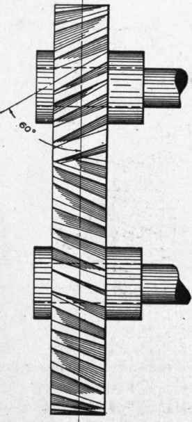
Fig. 275. Simple Form of Spiral Gears.

Fig. 276. Spiral Gears Whose Shafts Are at Right Angles.
Fig. 276 represents a pair of spiral gears whose shafts are at right angles to each other, and in which gear A has 8 teeth and the gear B has 16 teeth. Gear A is the driver; and from the fact that it has but one-half the number of teeth of the gear B, its speed must be twice as great. The angle of the teeth of gear A is 26 degrees 40 minutes. As the shafts stand at an angle of 90 degrees, we subtract the angle of the teeth of the gear A from 90 to obtain the angle of the teeth of the gear B, giving 63 degrees 20 minutes. The sum of the two angles equals the angle of the two shafts. That spiral gearing and worm gearing are closely allied is evident from this example. In analyzing the action of these devices, this fact should not be forgotten.
The necessary calculations for designing a pair of spiral gear3 may be illustrated by the following example: The gears are to be 4 and 16 inches diameter of pitch circle, and the shafts are parallel. The larger will have a lead of 96 inches; therefore the smaller will have a lead in the same ratio as the diameters, or 24 inches. Taking the large gear, 16X3.1416 = 50.2656 circumference, which, divided by the lead (96), gives .5235. Consulting a table of natural tangents, we find that this amount represents an angle of 27 degrees 40 minutes. The angle of the smaller gear will be the same.
If shafts are at other than right angles, this condition will change the angles of the teeth of spiral gears; and when the pitch diameters are alike and the numbers of teeth different, the angles will be different.
It is customary to use racks in connection with spiral gears, the gear being of comparatively short lead. This device is practically the screw and nut, the spiral gear acting as the screw and the rack as the nut. In designing racks for this purpose the teeth may be at right angles to the line of movement or at any angle between this position and 45 degrees. The shaft of the spiral gear used with a rack may be at any angle from parallel to the line of motion to 45 degrees. Angles of 35 degrees or less will produce better results under usual conditions. The pitch of the spiral, the number of teeth, and the angle of the shaft will govern the angle of the teeth of the rack. The teeth of the rack may be of concave form, similar to those of the worm gear if a large area of contact is required for heavy work. Otherwise they are usually cut in a straight line. The form of the teeth should be with straight lines for the side of the teeth, inclined 14 1/2 degrees.
Gear Cutting Processes
Two general processes are used for cutting the teeth of gears: milling and planing. Either of these processes may be used for cutting the teeth of spur gears, bevel gears, internal gears, racks, etc., but they are not equally adapted for spiral gears or worm gears.
Continue to:
My Books

