Tool-Posts
Description
This section is from the book "Machine Shop Work", by Frederick W. Turner, Oscar E. Perrigo, Howard P. Fairfield. Also available from Amazon: Machine shop work.
Tool-Posts
The tool is usually held to the carriage by means of a tool-post, shown in Fig. 118. The post consists of a piece with a slotted hole through the center for the tool B. A ring C slips over the post and rests upon the body of the carriage. This ring may be beveled as shown, to provide vertical adjustment for the point of the tool. The post has a collar D at its lower end, that goes loosely into a slot in the carriage. At the top there is a set screw E. When the tool has been properly adjusted by turning the ring C to give it the correct elevation, the set screw is tightened down upon the top of the tool. This raises the tool-post to a bearing on the under side of the slot, and clamps the whole firmly in position.
In setting the tool, it should be done with the cutting edge as far back toward the supporting ring as possible. If it has too much overhang, as shown by the dotted lines of Fig. 118, it will spring under the pressure of the work and will tend to chatter.
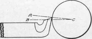
Fig. 117. Standard Setting with Cutting Edge of Tool a Little Above Center.
While this form of tool-post is used more than any other, there are certain objections to it. In the first place, changing the height of the tool-point also changes the angles of rake and clearance. These are supposed to be correct when the base of the tool is horizontal. Any change from this position will alter these angles materially. Again, this post is not rigid enough for heavy work. On lathes of over 30-inch swing, the style of tool-holder shown in


Fig. 118. Tool-Post Holding Tool to Carriage.
Fig. 119 is often employed. English manufacturers use it almost exclusively on all sizes. There is no provision for raising and lowering the point of the tool; and while this is not of serious importance on large lathes (30-inch and over), it becomes a matter of moment when turning the kind of work which as is usually handled in lathes of 14-inch and 16-inch swing.
The type of tool-post shown in Fig. 120 has two beveled rings to adjust the height of the tool.
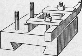
Fig. 119. Tool Holder for Heavy Turning.
The Lipe tool-post shown in Fig. 121, combines the good points of all the other types; the tool can be held by one or two screws as the character of the work may require, and the tool may be adjusted vertically and horizontally after being clamped down. The construction and operation of this tool-post are so evident from the illustration, that further description will not be given.
An entirely different method of adjusting the tool point is by means of what is called the elevating or rise-and-fall rest, shown in Fig. 122. In this type, there is a T-shaped casting carried on the upper part of the carriage, supported by trunnion screws at the front, and by an adjusting screw at the rear. With this is used a tool-post as shown in Fig. 118, with a plain ring. The elevating rest is used quite extensively on small lathes, but the convenience of adjustment is gained by a loss in rigidity. The cross-rail is slender; and the elevating portion, being supported at three widely separated points, lacks stiffness. As the effective swing over the carriage is limited by the height of the cross-rail and by the parts carried above it, they are made slender-in fact, too slender in many cases.

Fig. 120. Bevel Ring Tool-Post.

Fig. 121. Lipe Tool-Post.

Fig. 122. Tool-Post with Rise-and-Fall Rest.
Turning Tools
Side or Facing Tool. A very common form of lathe tool is shown in Fig. 123. It is used for squaring up the ends of shafts, facing shoulders, and similar work. While the ordinary forms will not remove a large amount of metal, they can, when made thick and heavy, be used for making roughing cuts on the surface of cylindrical work. The common form is made slender in order to work between the dead center and the piece in squaring up ends.

Fig. 123. Side or Facing Tool.
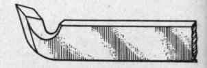
Fig. 124. Diamond Point.
Continue to:
My Books

