Appendix. Vol 2. Part 5
Description
This section is from the book "Turning And Mechanical Manipulation", by Charles Holtzapffel. Also available from Amazon: Turning and Mechanical Manipulation.
Appendix. Vol 2. Part 5
In a former account of the steam hammer, written by Mr. Nasmyth for the Civil Engineer's and Architect's Journal, Vol. VI. page 40, be first describes the circuitous mode in which the power was conveyed from the steam engine through intermediate gear and shifting, to the old helves or lift hammers, alluded to in the first volume, some of which lift hammers although weighing upwards of 6 or 7 tons, give by comparison ineffective blows on large masses, because from moving on a joint the rise and fall of the hammer is limited; and in forging thick works when the strongest blows are required, the hammer has the less space to fall. Mr. Nasymth then contrasts the above circuitous mode, with his own simple and " direct" means applied to the tame end. under an arrangement in which the largest works may with more consistency he made to receive the strongest blows.
Another comparison there also instituted is greatly favourable to the patentee, as he adds that although from various practical reasons, the dimensions of the old helves cannot be materially exceeded; the cylinders and appendages required in the new hammer admit of an almost unlimited increase in their magnitude, in order to meet the continual aggrandisements of engineering requirements.
Not« R. - To follow Note Q on page 196. (Mr. Nasmyth't Steam Pile Driving Engine.)
On this machine Mr. Nasmyth writes - " There are two grand or important features of novelty in this pile-driving engine, compared with all former con-trivances for the like purpose. In the first place by the employment of the steam hammer action, the steam is made to act direct in raising up and letting fall the hammer, or monkey, without the intervention of any rotative motion, while in the second place. another grand feature of novelty consists in the employment of the pile which we are about to drive, as the foundation or sole support of the apparatus A, B, C, fig. 971, so that by its resting on the shoulders of the pile, we have not only the effect produced by the blows of the hammer, (30 cwt. at 80 to 100 three feet falls per minute,) but we have also the entire weight of the apparatus A, B, C, equal to 3 tons assisting in a most important degree to force the pile down into the ground.**
" The pile to be driven is raised up and planted in its situation by the machine by means of a windlass worked by a ■mail detached steam engine at H, the apparatus A, B, C, is at the same time raised up and placed on the shoulders of the pile, like an extinguisher on a candle, the chain D, D, is then let free, so that the entire weight of A, B, C, shall rest on the pile; the steam is now let in from the boiler to the cylinder, by the jointed wrought iron pipe E, E, the hammer then sets to work with great energy, showering down its ponderous blows on the head of the pile at the rate of 80 to 100 per minute, at each blow the pile sinks and the machinery A, B, C, follows down with it, guided in its descent by clamps which loosely grasp a guide rail fixed on the side of the great upright, and which upright also retains the pile in true position all the way down."
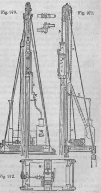
"Some idea of the rapidity with which piles are driven by this machine may be formed when we state that a pile of 60 feet in length and 14 inches square, can be driven 45 feet into stiff soil down to the rock below in 4 minutes, and such is the good effect resulting from the blows being given by a great mass, of 30 cwt. striking quickly but with small velocity of actual impact, that the pile head requires no hoop, and presents after being driven a neater appearance than it had when it was first placed under the hammer."
"This is a very important result, and the natural consequence arising from the employment of mechanical force in the right conditions for the purpose required, namely, in this case, striking a quick succession of blows with a large mass or hammer, but with small velocity of impact, by reason of the small height from which the hammer falls; the action of the ordinary pile driver-being quite the reverse of all these conditions. By inspecting the figure it will be seen that the entire machine is possessed of locomotive powers, inasmuch as it is mounted on wheels and moves along rails so as to pass onwards as the piles are driven in succession, it may be as well to observe that the apparatus A, B, C, is only raised up by the small fixed steam engine once per pile instead of once per blow, as in the case of the ordinary machine."
The author has not had the advantage of seeing Mr. Nasmyth's pile-driving machine, but he understands from eye-witnesses "that its rapidity is such as to excite a smile, from the almost marvellous manner in which this 'jack in the box,' (the hammer being concealed from view by the frame or casing,) performs its work, as it fulfils in 4 minutes, that which frequently required, by the old machine, a period of 36 hours, presenting a ratio in the time saved as 540 to 1, a ratio most egregious but true withal."
"A pile said to have been driven home, or as far as possible by the old pile driving engine (as the old ram then rebounded as from a solid rock), was driven a further quantity of 10 feet by the steam pile driver, until it had indeed met the solid rock beneath."
"The action of the machine is adduced as a most perfect evidence of the high importance of knowing under what modification we should use force in the accomplishment of certain duties; thus - if you want to split and shatter a pile into lucifer matches, then let fall cannon balls upon it from a great height, but if you want to drive the pile, then let the cannon itself fall on it, and that from a small height, and as rapidly as it can be effected, say 100 times in a minute, so that it may never give the pile a moment's time to set fast in the soil."
Note S, page 202. - To follow the third paragraph.
(The Oliver, or small lift hammer.)
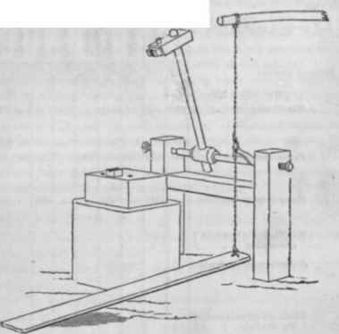
Fig. 973 represents a species of lift hammer worked by the foot. The hammer head is about 2 1/2 inches square and 10 long, with a swage tool having a conical crease attached to it, and a corresponding swage is fixed in a square cast-iron anvil block, about 12 inches square, and 6 deep, with one or two round holes for punching, Ac The hammer handle in about 2 to 2 1/2feet long, and mounted in a crow spindle nearly as long, supported in a wooden frame between and screws, to adjust the groove in the hammer face to that in the anvil block. A short arm 5 or 6 inches long, is attached to the right and of the hammer axis, and from this arm proceeds a cord to a spring pole over head, and also a chain to a treadle a little shore the floor of the smithy. When left to itself the hammer handle is raised to nearly a vortical position by the spring, and it is brought down very readily with the foot, so as to give good hard blows at the commencement of moulding the objects, and then light blows for finishing them. The machine was used when the author first saw it, in making long stout nails, intended for fixing the tires of wheels, secured within the felloes by washers and rivetting; the nails were made very nicely round and taper, and were forged expeditiously.
Fig. 973.
Note T, page 226. - To follow the fifth line. (The Manufacture of Wrought Iron Tubes.)
The authors attention has been drawn to the contents of pages 225 and 226 of his first volume, referring to the manufacture of wrought iron tubes, associated with a regret, that he had not set forth more fully and historically the progressive steps through which this interesting and important manufacture has arrived at its present state of perfection.
Upon this hint the author requested Mr. Prosser, with whom the suggestion originated, to point out the errors of mode and date that ho had committed, and which correction Mr. Prosser has most kindly rendered in the accompanying synoptical table here inserted without alteration.
Continue to:
My Books

