Section II. - The Cylinder And Surface. The Armrest. The Cylinder
Description
This section is from the book "Turning And Mechanical Manipulation", by Charles Holtzapffel. Also available from Amazon: Turning and Mechanical Manipulation.
Section II. - The Cylinder And Surface. The Armrest. The Cylinder
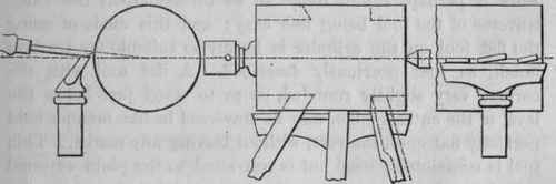
The hardwood cylinder, figs. 408 to 410, mounted between centers or in a plain chuck, as previously described, is roughed and then turned true with the gouge, which may have either a long or short handle. A series of separate cuts, commenced at the end and led one into the other for the entire length of the work, and repeated if that be much out of truth, reduces its irregularities leaving it concentric and in ridges. The gouge lies on its side, and may be held and used exactly as on the softwood cylinder.
The ridges left by the separate cuts may then be reduced and connected into one line, by traversing the gouge along the rest, lying on its back, the hands and tool still in the position for softwood. The hardness of the material however, rather interferes with the equal traverse of the tool, which is liable to jerk from one ridge to the next or completely over it. The traverse is easier and more regular, when both hands are shifted to the blade, to hold it after the horizontal manner, with the left hand around the pedestal of the rest, keeping the shaft of the tool still in the sloping or overhand position required by the gouge, as in fig. 335. The center of the edge is then applied to reduce each ridge seriatim, and subsequently the gouge still held in the same manner, is traversed from end to end, until the work has acquired a moderate parallelism.
The hardwood cylinder is turned smooth and parallel with the flat tool, held in the horizontal manner, its under surface at first lying flat on the rest, with the shaft at about the angle fig. 408. The tool is retained at one spot until it has turned a portion equal to its own width, being made to cut by simple pressure or by lowering the handle. It is then withdrawn and shifted along the rest rather less than its own width, this second cut merging into the first; a similar third cut is then made, and so on for the length of the cylinder. The series of separate cuts leaves the work nearly the finished diameter, as tested by the callipers, but with numerous rings or lines upon it, breaks of surface continuity caused by the corners of the tool at every replacement.
Short cylinders, such as the plain fitting for the lip of a box, that are less than the width of the tool have no such marks, as the tool requires no lateral displacement, but marks from the separate cuts are not easily avoided upon greater lengths; they are obliterated by the subsequent traverse of the tool in finishing the cylinder to size and parallelism. The perfectly straight edge of the flat or other rectilinear edged tool, cannot practically be traversed, entirely in contact with the cylinder when lying flat upon the rest, without the corners catching or leaving fresh marks. The tool still held in the same manner, is therefore very slightly tilted upon its leading under corner, during its entire traverse, fig. 410; when it cuts by the middle of the edge, with the corners free of the work. When travelling from right to left, the tool is tilted on the left corner, its left side embedded in the left thumb, which, itself pressed on the rest, yet allows the corner of the tool also to touch it;
Fig. 408. Fig. 409. Fig. 410.
the following side of the tool is raised just off the rest, but is embedded in the forefinger which is pressed upon the rest. A uniform vertical angle is maintained during each entire traverse of the tool, and although the latter touches the support by only one corner, it is held even more securely, from being cushioned between the thumb and finger, and is less subject to vibration, than when, under similar guidance, it lies flat on the rest. The inclination and positions are reversed, when the tool is traversed from left to right.
Very little inclination suffices to free the corners, and no more is given; for, as the face of the tool departs from the horizontal line, so far the guidance of its rectilinear edge is diminished, and the tool, analogous to the chisel, becomes an oblique tangent to the circle. Hardwood also does not permit nearly the same free traverse of the tool, as with the chisel on softwood, so that if the flat tool be too far tilted, the resistance of the material interferes and tends to reduce and vary the inclination; the effect of which is to turn the work into a succession of slight hollows instead of a straight line. On the other hand, increasing the inclination is an advantage in correcting errors, for which purpose the tool is tilted more or less, so as to take effect only upon the high portions of the line, the traverse of the tool being interrupted and recommenced as desirable during the corrections. As the cylinder approaches truth, its straight line materially assists both the traverse of the tool and the maintenance of its uniform angle, during the fine continuous shavings taken in finishing the work.
The flat tool may also be traversed without leaving marks upon the cylinder, when lying quite flat upon the rest, if the leading corner of the cutting edge, be held just free of the work, in the manner explained for the surface fig. 419. The work is perhaps rather liable to be turned taper, the exact traverse of the tool being less easy; and this mode of using the flat tool on the cylinder is hardly so suitable for truth of finish, as that previously described. A flat tool with the corners very slightly rounded, so as to stand just below the level of the cutting edge, may be traversed in like manner held perfectly flat upon the rest, without leaving any marks. This tool is occasionally used but is restricted to the plain external cylinder and surface; for, as the true straight edge of the flat tool applied to the work without lateral movement, produces a copy of itself, a tool which although to all appearance flat, does not produce a straight line, is a source of frequent inconvenience. The cylinder may also be turned smooth by the bevil tool, or the end of the right side tool; these are hardly so convenient as their shafts require a horizontal angle, in other respects their manipulation is similar to that of the flat tool. They are required for such purposes, as the internal corners and contiguous portions of the cylinder and collar, indicated by the dotted lines fig. 409. The tools travel down the surface, and arriving at the corner, are withdrawn cutting a short distance along the cylinder, and are then exchanged for the flat tool.
Continue to:
My Books

