Plan No. 2: Inside House Drainage
Description
This section is from the book "A Treatise On Architecture And Building Construction Vol4: Plumbing And Gas-Fitting, Heating And Ventilation, Painting And Decorating, Estimating And Calculating Quantities", by The Colliery Engineer Co. Also available from Amazon: A Treatise On Architecture And Building Construction.
Plan No. 2: Inside House Drainage
191. Fig. 72 shows, in sectional elevation, a system of drains, soil, waste, and vent pipes for a city building. All of the sewage from the building is discharged into the street sewer a by a 6-inch fireclay pipe b, which is broken to show that the sewer is farther away from the building than it appears in the cut. A 5 or 6 inch iron disconnecting trap c is placed just inside the cellar wall. The 5-inch house drain d is run along the face of the cellar wall. A 4-inch pipe, furnished with a deep seal trap e in the cellar, carries away surface water from the catch basin e1 in the front area. A 5-inch fresh-air inlet pipe f takes a supply of fresh air from the street curb by means of a perforated post inlet i, as shown, instead of a plain grating flush with the pavement. A 4-inch deep seal trap g disconnects the back area surface water box h and the roof leader k from the house drain. The rain-water pipe j1 and the tank overflow pipe j both deliver into a rain-water head upon the rain-water pipe k.
The fixtures in the basement floor are a kitchen sink, a set of three laundry tubs, and a refrigerator. The fixtures upon the first floor are a butler's pantry sink, a corner wash basin, a water closet, and a urinal, the closet and urinal both being flushed from small tanks overhead. In ordinary private house work the three latter fixtures would be omitted. They are connected up in the drawing only for illustration, as they may, in exceptional cases, be employed. The fixtures on the second floor are two wash basins, a Roman bath, and a siphon-jet closet. The fixtures on the third floor are two wash basins, a French bath, and a front outlet washout closet.
On the top floor, for the servants' use, is located a common iron bath, a plain wash basin, and a short hopper closet. A rectangular, copper-lined, wooden house tank l is also placed on the fourth floor, high enough to supply the small tank for the hopper closet, and a hatch m about 20 inches by 30 inches is made on the roof for access to the tank.
The long hopper closet n is fitted up in a small "lean-to"


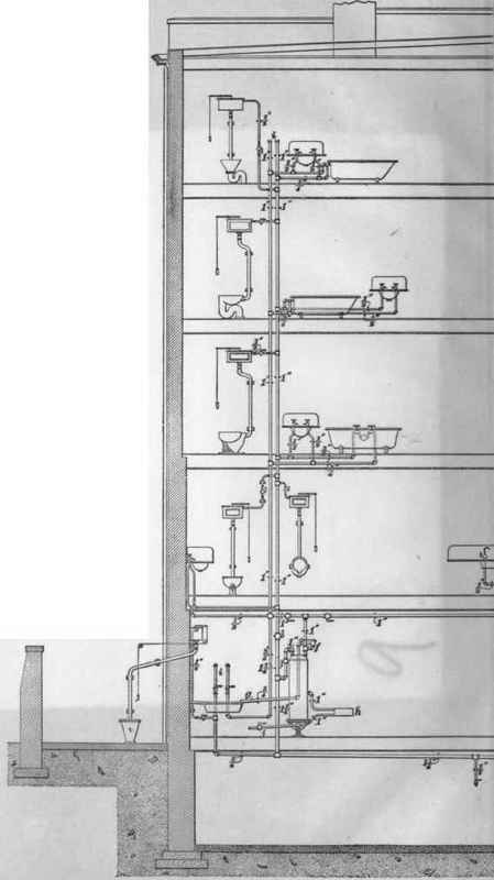
Fig.

apartment in the back area, or basement, and opens into the back area. The tank l, for this closet is fitted up inside the building, and the trap is underground. This is to guard against frost.
The 4-inch soil-pipe stack p is run up full size to the roof of the building, increasing to 5 inches as it passes through the roof. The 1-inch vent stack q, corresponding to p, also increases in diameter as it passes through the roof; its base joins the house drain at an angle of 45 degrees, so that any rust falling down may slide into d, and thus be washed away.
The 3-inch waste-pipe stack r is carried full size up to the roof, and increased to 4 inches as it passes through it For purpose of economy only, the corresponding 2-inch vent pipe s joins r above the highest fixture, instead of passing separately up to, and through, the roof.
Brick piers p1 are built under the vertical stacks to support them. The 1/2-inch telltale pipe t, l 1/4-inch safe wastes u, and refrigerator waste u1 discharge openly into a sink in the cellar. The safe wastes are trapped by making a coil on the end of the pipe as shown, and are carried full size up to, and through, the roof, to prevent odors from entering any of the upper rooms through them. The vent outlets above the roof should be carried up a few feet higher than shown; they are shortened in order to avoid making the drawing too large. The waste pipe from the Roman bath on second floor is dropped down and made to flush the urinal waste; but it may join the stackn p if desired.
Continue to:
My Books

