Plan No. 1: Outside House Drainage
Description
This section is from the book "A Treatise On Architecture And Building Construction Vol4: Plumbing And Gas-Fitting, Heating And Ventilation, Painting And Decorating, Estimating And Calculating Quantities", by The Colliery Engineer Co. Also available from Amazon: A Treatise On Architecture And Building Construction.
Plan No. 1: Outside House Drainage
189. Fig. 71 shows in plan and sectional elevation a system of drainage suitable for an isolated building. Water is assumed to be scarce, and the rain water falling upon the roof of the building is collected and stored in a brick and cement cistern. The sewer pipe is supposed to be very long, and to have a very slight fall towards its outlet. To keep the drains clean with a minimum expenditure of water, the waste water from some of the baths and wash basins is collected in an automatic flushing tank and discharged, periodically, for flushing purposes. Of course, when this is done the bath and basin stacks must be carried separately up to and through the roof, and have no connection with the closet, soil, or vent pipes. It will be noticed that all the pipes are run immediately through the main walls and underground. This avoids running horizontal pipes in the basement or under the floors of the building, thereby reducing the danger from leaks to a minimum.
The building is shown in block plan, its main walls being shown at A.
The 6-inch earthenware pipe a is the house sewer proper. It conveys all of the sewage from the building to a suitable outlet. The main disconnecting trap b is built in a brick manhole. An inspection piece into which the drains d discharge, and the fresh-air inlet e joins, delivers into the trap. A closed inspection piece is built into the manhole f.
An automatic flushing tank g is connected to the highest end. This receives discharge from the bath and basin waste h. The pipe i, led to a convenient point, is a fresh-air inlet to g, while h acts as an outlet.
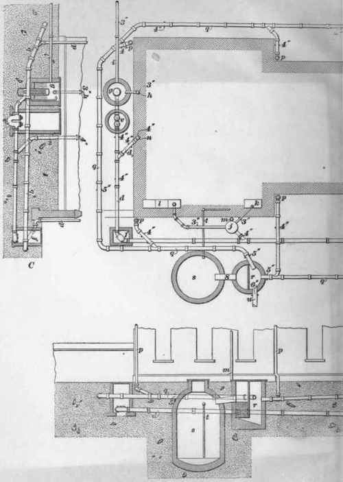

A grease trap j intercepts grease, etc. from the sink k and laundry tubs l, and is ventilated to the roof by a 3-inch pipe m, a few holes being made in the cover for an air inlet
The branch drains d1, d1 connect the soil-pipe stacks n, n to the main drains. The discharge from baths and basins connected to the waste stack h1, enters the drains direct.
The roof water falls in the leader or conductor pipes p into the selected stoneware rain-water pipes q. These pipes convey it to the filter r through which it must flow before entering the cistern s, from which it is drawn to the build ing by a pump attached to the suction pipe t. An overflow for the filter, that is, for the cistern, is shown at u.
The trap v disconnects the flushing tank from the drains, so that when the tank is empty it will not be flooded with drain air.
A small air pipe which turns over in the tank g, prevents air lock between g and v. A handhole w is placed upon the drain for easy access.
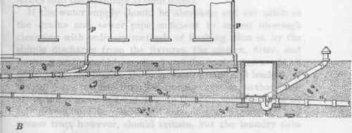
190. Should the water supply to this building be abundant and the roof water be permitted to flow to waste, the best method then would be to run all the rain-water drains into a flushing tank, and all the discharge from the several pipe stacks into the drainage system direct.
If the water supply should be abundant and the pitch of the drains and sewer pipe sufficient to insure thorough cleansing with ordinary methods of flushing, that is, by the simple discharge from the fixtures, the cistern, filter, and flushing tank would be omitted and the roof water would all deliver into the drains, the rain-water drains and leaders, of course, being trapped from the drainage system, so that drain air or sewer gas could not flow up the rain-water leaders, or conductors, and be discharged into or near windows. The grease trap, however, should remain, but the laundry tubs need not deliver into it.
Continue to:
My Books

