Making Draw Broaches. Cutting And Turning To Size
Description
This section is from the book "Modern Shop Practice", by Howard Monroe Raymond. Also available from Amazon: Modern Shop Practice.
Making Draw Broaches. Cutting And Turning To Size
No general method can be given for making all forms of draw broaches, as the desirable method depends on the form of the finished tool. If the broach is to be used for producing square, hexagonal, or other holes, with round corners, from a round drilled hole, select steel adapted to the individual job. Cut the steel to length, then center and square the ends; after which it should be rough-turned, and the shank turned to finish size, which is generally the size of the drilled hole. However, if the end of the shank is to fit some holding device that goes with the machine, then that portion must be turned to that size as shown in Fig. 400. This, of course, must not be larger than the drilled hole.
The balance of the piece should now be turned to the largest diameter of the broach plus a small amount for finish, and tapered from the teeth nearest the fastened end to within four teeth of the opposite end; this end should be straight in order that the last four teeth may all be of a size to allow for wear, Fig, 390. Having the four teeth of finish size insures correct sizing of holes, even after the cutting teeth have been sharpened several times.

Fig. 400. Typical Pull Broach Showing Method of Holding End Courtesy of J. N. Lapointe Company, New London, Connecticut.
Annealing
Many tool-makers who make a specialty of broaching tools always anneal the broach after the teeth have been blocked out. After annealing, the teeth are cut to depth and the broach finished and hardened.
Cutting Teeth
If the broach is to produce a square hole with round corners, Fig. 394, the teeth may be first produced on the lathe on the round piece, Fig. 391, with a tool that will produce a cut of the desired form and depth. The spacing can be obtained by means of the lead screw, or, with a spacing block and clamp with a set screw, Fig. 401. The clamp should be attached to the bed of the lathe and the screw set against the space block as shown. The block, the thickness of which corresponds with the desired pitch of the teeth, is removed, and the carriage moved along against the screw. In this way, the teeth are spaced exactly alike for the entire length of the cutting portion of the broach.

Fig. 401. Spacing Block and Clamp.
Before the broach is removed from the lathe, the tops of the teeth should be backed off for clearance, as shown at c, Fig. 391, by means of a fiat-nosed tool. After all the teeth have been backed off, the broach should be placed between the index centers of the milling machine, and one center raised or the other lowered to the taper of the broach and the flats milled. The large end-that is, the last four teeth-should be milled to the desired dimensions parallel to the axis.
The teeth on the flat portions may now be produced by milling or planing, to correspond in shape and depth to those on the round corners.
Filing Teeth
It is necessary to have the face and the back of the tooth smooth in order that chips will be cleared readily. This can be secured by filing, and should be done before the top surfaces that make the clearance angle are filed. Previous to filing the surfaces of the clearance angle, apply copperas in order that the workman may see where he is filing. File to the cutting edge, but do not remove any stock from the edge, because if one tooth is made short, the next tooth must do double duty. As previously stated, the four teeth at the large end of the broach should be of equal diameter if the tool is to hold its size.
Pitch Of Teeth
The pitch of broach teeth cannot be stated arbitrarily, for the distance from one tooth to the next depends in a great measure on the amount of stock to be removed, the length of the broach, and the thickness of the piece to be broached. The following formula, however, is used by some manufacturers of broaches for use under average conditions:
P = √Lx0.35 where P=pitch, or distance apart of teeth; and L = length of hole to be broached. For example, if a broach is to be made for broaching a hole 4 inches long, the distance between the teeth would equal 2X0.35, or .7 inch, approximately. In the case of a broach of large diameter, it is possible to cut the teeth deep and a little closer together than if the broach were of smaller diameter, as in the latter case the teeth must be shallower to give strength to the broach. It is always necessary to design the broach with the teeth so spaced and of such depth that the space between them will hold the chips removed, for otherwise the chips would wedge themselves between the broach and the walls of the hole, thus tearing the surface of the walls, and in all probability breaking the broach.
Size Of Teeth
The variation of size of adjoining teeth cannot be stated arbitrarily. Under average conditions, an increase in size of from .001 to .003 inch works well on steel, and from .002 to .004 inch on cast iron or brass. Yet working conditions and the character of the material make it possible and advisable to change these amounts of increase in size at times.
If the broach has long cutting teeth, it is advisable to nick them to break the chip, as the long chip, especially if it is steel, would be likely to cause trouble. When nicking the teeth, make sure that no two adjoining teeth have their nicks in line.
Angle Of Teeth
The face f, Fig. 391, of the teeth of broaches is many times made at right angles to the axis of the broach. A tooth cut as shown at a, however, will require less force to pull it through the work if made at an angle, yet under ordinary conditions the shape shown at 6 is considered the better one.
The clearance angle, c, is generally about 2 degrees, although at times but 1 degree is given.
The teeth of broaches are sometimes made at an angle, as shown in Fig. 402. In the case of square and rectangular broaches, teeth on opposite sides are made at opposite angles in order to balance the cut.
Hardening
When hardening broaches, it is necessary to heat them uniformly their entire length, a process best carried on in an oven furnace or in a piece of pipe in an ordinary furnace. In order to get a uniform temperature, the piece should be turned frequently. When it has become uniformly heated to the proper temperature, plunge it vertically in a bath of warm, not hot, water in which a quantity of salt has been dissolved, and work up and down until cooled to the temperature of the water, when the broach may be removed and tested for straightness. If it has sprung in the operation of hardening, it may be straightened in the following manner: Place the broach in a screw press or a drill-press table on two blocks of hard wood, then, with a spirit lamp or bunsen burner, heat it until lard oil on the surface smokes; now, with a third block of wood between the work and spindle of machine, apply pressure by means of the spindle until the tool is straightened. It will be necessary to do all the straightening before the temperature drops much, or the broach will break. After the straightening, the temper may be drawn. Some hardeners, who are quite skilful in this particular line of work, straighten and draw the temper at one operation. Broaches made from oil-hardening steels are heated as described above and hardened in oil. Broaches made from low-carbon open-hearth steel are packed in charred leather in a piece of gas pipe, the ends of which are sealed, and the whole subjected to a red heat for several hours, the time depending on the size of the piece. When the carbon has penetrated to the desired depth, the broach is removed from the pipe and plunged vertically into a bath of hardening oil; or, if a harder effect is desired, into a bath of lukewarm water.
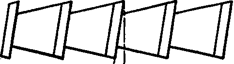
Fig. 402. Diagram Showing Angle of Broach Teeth.
After hardening, the broach should be tested for straightness; if it has sprung, it should be heated and straightened, as previously described, and the temper drawn to a light straw color.
Long Broach Vs. Short Broach
Generally speaking, the length of a broach depends on the amount of stock to be cut out of the hole, and the capacity of the machine. Some broach-makers, however, believe it is economy to use several short broaches instead of one long broach, even where the capacity of the machine makes it possible to use a long one, maintaining that long broaches are more costly to make, and more likely to break when in use. The advisability of either depends on so many factors that are peculiar to the individual shop, that it is not possible to make any general statement that will fit all cases.
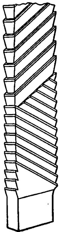
Fig. 403. Typical Push Broach.
Push Broaches
Broaches of the form shown in Fig. 403, are called push broaches, and are used in special presses having an adjustable stroke of from 1 1/2 to 12 inches. It is generally necessary to use several broaches in finishing a hole, especially if they are short. At times it is desirable to use a long broach in a press having a comparatively short stroke. This may be accomplished by using blocks. First drive the broach into the work as far as possible with the stroke of the press; then, when the ram is at the top of the stroke, insert a block the thickness of which is equal to the stroke of the press between the ram and the top of the broach. At each successive stroke of the press, use a thicker block.


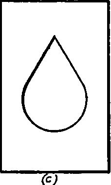
Fig. 404. Progressive Punchings of Keyseating Machine.
When broaches are used in a press, it is always advisable to use a driver having a V-shaped opening in face.
Keyseating Machine
For many jobs a keyseating machine is an absolutely essential part of the equipment. Where work is done in small lots, it is frequently advisable to use this machine instead of a broaching machine, as the cost of cutting tools is but a fraction of the cost of a broach.
At times this machine is used to remove a portion of the stock before broaching, as is the case with the piece shown in Fig. 404. A hole is drilled in the piece, as shown at a; the piece is then placed in the keyseating machine and the hole cut to the form shown at b, after which it may be brought to finish size and shape c by broaching.
Irregularly shaped holes that are larger at one end than at the other, as shown in the circular piece, Fig. 405, are easily machined in a keyseating machine by the use of properly shaped cutting tools and rightly designed holding fixtures.
Fig. 406. Keyseating Machine and Sample Keyseats in Taper Hole Courtesy of Mills and Merrill, Saginav, Michigan.
Continue to:
My Books

