Axle-Tree. Continued
Description
This section is from the book "The Engineer's And Mechanic's Encyclopaedia", by Luke Hebert. Also available from Amazon: Engineer's And Mechanic's Encyclopaedia.
Axle-Tree. Continued
This lubricating arrangement is, evidently, applicable to both kinds of axles, but the other part of the contrivance, which has for its object the better security of the wheel, and the prevention of end-play, so as not to allow the escape of oil from the box, nor the admission of dust, or other impurities into it, applies exclusively to the mail axles, or those which are kept in the box by means of screws at its inner end. Three wrought-iron screws are cast into three legs on the box, two of which are shown in the figure at n ft When the axle is introduced into the box, the conical part i fits the conical part j, and tends to preserve the leather collar between i and k, while the loose plate m fits upon, and is firmly secured by, the screws n n to the end of the box, and thus the box is kept in its place by the collar k, which works in the recess l, and the wheel is prevented from coming off by the plate mm.
Formerly, this plate was fastened by short screw-bolts passing through it and the legs of the box, a method which was found defective on account of their liability to shake loose by the constant jarring of the coach. To remedy this, and to facilitate the removal of the wheel when desirable to take it off, the back plate was fastened by long bolts passing through the nave and screwed on the outside; but this, too, was found to be objectionable, on account of the injury caused to the nave by the bolt holes, and their occasional removal, when the wheel required taking off; and to remedy these defects, is the object of the invention which we have been describing. An objection to the present mode of locking the fore wheels of four-wheeled carriages from the centre, is, that in sharp turns, the fore-wheels are brought so nearly in a line with the perch, that the coach has little better than three points of support, and is, therefore, very liable to be overturned. Another inconvenience arising from this method is, that it requires the fore-wheels to be made much smaller than the hind ones, which greatly increases the draft, and has, at the same time, an inelegant appearance.
These objections are obviated by a construction, for which Mr. Ackerman took out a patent in 1816, the principle of which is as follows: The fore axle-tree of the carriage does not turn, but is fixed to the perch in the same manner as the hind one; each of the fore wheels revolve upon one end of a short arm, the other extremity of which is turned up at a right angle, and turns in a hinge joint at each extremity of the fixed axle-tree; from the back of each of the short axles, a lever projects, and the coach-pole being carried back beyond the pin in the fixed axle-tree, an iron bar connects the extremities of the two levers, and of the coach-pole, so that when the coach-pole turns upon its fulcrum, the short axles turn upon their upright arms as centres, and if the length of the connecting bar be equal to the distance between the vertical arms of the axles, the two wheels will always stand parallel to each other; but by varying the length of the connecting bar, the inner wheel, in turning, may be made to perform a shorter curve than the outer one. The cut represents one of these arms, Fig. 1 being a front view, and Fig. 2 a side view; a is a portion of the fixed axle-tree; b the horizontal arm upon which the wheel revolves; c the vertical arm; d the lever; e connecting bar.
In the diagram, Fig. 3, the dotted lines represent the position of the fore wheels when locked to the utmost extent; and the other lines, their position in the same circumstances, with axles on Mr. Ackerman's plan, from which it will be seen that the latter afford a much wider base to the carriage than the former; the wheels may also be made of nearly the same diameter as the hind wheels, without hanging the body of the carriage higher. A B is the line of the perch. Patents for axle-trees upon the same principle have since been taken out by Miss Knowles, and by Mr. Mason, varying slightly in the details. There have been many plans proposed for diminishing the friction at the axle by means of anti-friction rollers; but, from the experiments made upon rail-roads, of the resistance of running wheels thereon, as compared with those on common roads, it appears, the amount of friction of the axes of wheels made in the common way, was so extremely trifling in comparison with the resistance at the peripheries, that it became absolutely impossible to gain any practical advantage of moment by such a reduction of the axles as they are susceptible of.
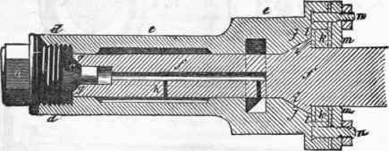
It should be borne in mind, that the weight of the carriage must be supported on some of the rubbing, or revolving, parts; and these parts being already, comparatively, very small, their surfaces cannot be much reduced without impairing the requisite strength. By anti-friction rollers, we only transfer the friction, without materially lessening it; whilst we incur complexity, increased expense, and greater liability to derangement. For these reasons, we shall notice only one out of the many contrivances on this subject; it is the invention of Mr. Spong, and is selected as being the simplest in construction, a e is the revolving axle-tree made square at a for inserting into the nave of the wheel, to which it is made fast, by means of the nut b screwing it close up to the shoulder c. The circular part of the axle revolves in two bearings; one in plummer blocks at d, regulated by screws at l; the other at e, in a solid piece projecting from the axle-tree f. The thick end of the axle at o, carries an anti-friction roller k, which turns on a short pivot, or axis, at i (shown by white dots).
Oil is applied to the bearings and axis, by means of perforations at h h, which are closed by screw stoppers.


From an account of some experiments made by Mr. H. R. Palmer, now engineer to the London Dock Company, it would appear that the forms of the cavities, or interstices, through which the lubricating matter is applied to the axes of wheels, is of considerable importance. During a succession of experiments occasionally for many months, he invariably perceived that when fresh oil was applied to the axles of the carriage, the resistance was increased, and it required the ordinary motion of the carriage for several days to restore the resistance to its usual standard. No other presumption occurred to account for this fact, than the possibility of the oil being better adapted for its office after being some time exposed to use. It was suggested to him that the oil became thickened, or less fluid, after exposure to the air, and was therefore better able to resist the contact of surfaces. In order to prove this, he thickened some oil artificially, by the admixture of a small quantity of bees'-wax, but the appearances were the same as before.
It then occurred to him, that there was not sufficient play, or difference of diameters, between the axle and the nave in which it worked; he therefore had the axles slightly reduced.
On again measuring the resistance, he found circumstances as before, but differing in amount, the resistance being slightly increased. He was by this time convinced that the quantity, rather than quality, of oil, occasioned the appearances; to prove which, the axles were made perfectly clean, and then simply moistened with oil by the finger, previous to inserting them in the wheel. In this state the resistance was again measured, and found to be similar to the standard usually observed after the carriage had been some days in motion, as before described. It being, then, proved that the quantity of oil occasioned the difference of resistance, the following solution of the manner in which the additional quantity could produce such an effect, appeared reasonable. Let ABCD, F g. 1, represent the circle of the hole in the nave of the wheel, and E C the section of the axle. The circle E C touches A B C D only in the point C. A very acute angular space then remains between A E and C on either side of E C.
If that space be filled with oil, the oil may be considered as a wedge, and if the outer circle be set in motion, that wedge will endeavour to pass the point C But it cannot pass in its present form without raising the circle E C; but E C having the weight of the carriage upon it, would resist its passage. Now this continual and unsuccessful endeavour to pass the point C will occasion an impediment to the motion. To put this solution to the test, the axles were formed as in Fig. 2. A B C D is the hole in the nave as before, and E F C G the section of the axle. The lower semicircle of the axle here corresponds with, or is parallel to, the outer circle, but no further, because if it corresponded throughout the circle, the axle would be liable to jamb, as other experiments have proved. The coincidence then ceases abruptly, as at B F G D, and the space above which contains the oil is not angular, but the quantity of oil which is to pass toward the lower semicircle is determined at B or D. On measuring the resistance with the axle thus formed, he found it not increased by any quantity of oil that might be inserted; but by dispensing with the angular space, and consequent wedge-like action of the oil, the resistance was one-tenth less than the former standard.
In cases where the difference of diameters is considerable, he does not apprehend the obstruction from the quantity of oil would be of consequence; but it is desirable to make the bearing surfaces nearly to correspond, to obtain a greater width of touching surface, and the more perfectly to govern the motion. The form of axle just described is, in fact, the converse of a well-made plummer block, used in machinery.
Fig. 1.
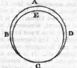
Fig. 2.

Continue to:
My Books

