Horology. Part 12
Description
This section is from the book "The Engineer's And Mechanic's Encyclopaedia", by Luke Hebert. Also available from Amazon: Engineer's And Mechanic's Encyclopaedia.
Horology. Part 12
Figs. 1 and 8 show the impendent, made of the same metal as the case; it turns freely on a piece of steel g, Fig. 8; this steel arbor has a small knob on one side, h, shown at Figs. 1 and 8, to prevent the impendent from slipping off; on the other end it is split to receive the end of the chain which is pinned on; the pendent of the case is perforated, through which the chain passes. l shall next describe the manner it is to operate, and how it is to be put on the winding up arbor. When the barrel ratchet before mentioned is put on the square arbor, the recoiling spring is put on the barrel pulley, and placed over the barrel ratchet, so as to act on its click; the chain, which is no longer than to produce one revolution of the pulley, is put through the pendent, and hooked on to the pulley: the stud is then hooked on to the recoiling spring; by this stud the recoiling spring is set up one turn, more or less, and the stud is screwed on the plate. To wind up the watch, the impendent is drawn from the pendent as far as the chain will permit it; the recoiling spring will bring the impendent back again to the pendent; and this operation is repeated till the impendent remains on the pendent, and cannot be more drawn from it, which indicates that the main spring is wound up.
When the works are to be wound up by a fusee arbor, the ratchet, which keeps the maintaining power, is on the fusee itself; the fusee arbor, squared, is on the same side of the plate as the going-barrel under the dial. The recoiling ratchet, Fig. 4, is put on the fusee arbor; its click and spring are on the barrel pulley, Fig 6. Here it is to be observed, that when any works are to be wound up by a fusee, the fusee with the first wheel and its arbor returns back again, which is not the case with a going barrel, h is the relieving click, which has a double action; first, it acts as the recoiling click, by its action in the ratchet; secondly, it acts as a reliever of the said click; it is planted on the under side of the barrel pulley, Fig. 6, with its spring, and must be made in the form shown in the drawing. That part which is near the edge of the barrel pulley has a small pin, which pin goes through an aperture of the barrel pulley into the groove where the chain lies. When the works are wound up, the impendent rests upon the pendent, and the chain lays round the pulley, which is the same as with the going-barrel.
The pin of the relieving click, which goes into the groove of the barrel pulley, receives a pressure from the chain; it brings the click part out of the ratchet, and gives free action to the ratchet on the fusee arbor to return back again without any drag or incumbrance of the click. l, Fig. 1, is the finger touch: it is made of gold, or some metal which will not rust. By referring to the drawing, it will be seen that it is a kind of cup with a milled edge, and the minute-hand is fastened to it: when the hands are to be set, a slight pressure with the end of the forefinger is required to turn the hands. In case it is desired to have a watch or clock wound up in one pull, the multiplying of the turns of the chain round the barrel pulley will have that effect.
Fig. 4.
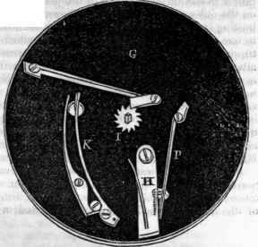
Fig. 6.


The engraving on the next page exhibits a simple but very ingenious contrivance, termed by the inventor, (Mr. Knight, of Birmingham,) the "Patent Duty Register," which is designed to operate as a check upon public watchmen, and to ensure vigilance upon their part, by causing them to register the time at which they go their rounds, in a manner that will admit of no deception. Its uses, however, are not limited to this purpose, as it is equally serviceable as a check upon servants in general, and as a conviction of the correct information which it will infallibly afford to employers, it has a tendency to ensure punctuality on the part of those from whom it may be required. The train of wheel-work in Mr. Knight's machine being similar to those in ordinary clocks, the invention must be regarded as an addition or appendage, which is capable of being applied to clocks already made, as well as to those which are manufactured purposely to receive the new combination. The only essential variation consists in causing the circular dial-plate, which is usually fixed, to revolve, and the hand or index, which usually revolves, to be fixed.
This stationary index is placed at the top of the circle, and the hours, as they successively come under it, denote present time.
This index forms part of a bended lever, the fulcrum of which is in the interior or back of the clock, and the other extremity of it is attached to a bell wire, with suitable cranks to carry the line of communication to the required place, where a handle is connected to it, for the individual who is upon duty or guard, to pull at stated times; this operation raises the power end of the lever, and depresses the index, which makes a mark upon a temporary scale of hours fixed to the dial-plate, and indicates the precise time at which each mark was made. As the lever has only one centre of motion, it follows that the index, which forms a part of it, moves in the arc of a circle, and consequently would only strike upon a point; but to enable it to make a line, there is a spring joint where the lever is bent to a right angle, which allows the extremity of the index to move in a right line over the plate. The clock face has two concentric circles of hoars, the outer permament and of a full size, the inner temporary, and of small dimensions.
The latter is an engraved print, the divisions upon which correspond radially with those on the outer circle, and it is intended that a fresh card should be put on the dial-plate every day; it is contrived so as to enable them to be put on with accuracy and expedition; the card taken off forming a register of the duty performed, a is the revolving metal dial-plate ; b the revolving card ; c an ornamental metal shield, to confine the card down to the plate, which is fixed to it by means of a thumb screw d; l is the marker, formed of a little sharp-edged wheel, revolving in a cleft at the extremity of the index, like a spur rowel, only without teeth ; at f is the spring joint of the lever, before mentioned, forming the upper extremity of the lever. On depressing the lever, the end f takes the position of e, while c descends on the card dial and makes the mark. In our drawing, .the time expressed is two o'clock; and if the handle be pulled, the index will descend from the position represented, and make the line drawn between the II, marked s ; there are two other lines made upon the drawing, also marked s, which are intended merely as examples to show that such marks were made at the time expressed by the person on duty.
Continue to:
My Books

