Ship. Part 4
Description
This section is from the book "The Engineer's And Mechanic's Encyclopaedia", by Luke Hebert. Also available from Amazon: Engineer's And Mechanic's Encyclopaedia.
Ship. Part 4
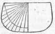
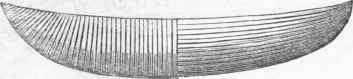
The mode of proceeding is first to form a model of the required dimensions, and regulate the symmetry of the subordinate arrangements accordingly; this done, the model is cut across, by which the form and proportions for the mould are exactly obtained, as shown in the annexed Fig. 1. The moulds are (Perspective View of Moulds set up.) together the perfect shape of the intended vessel: they are shown in Fig. 2. A longitudinal layer or course of planks is then fastened to the moulds all round; namely, bottom, sides, and deck; sheets of tarred paper are then laid on, and a second course of planks is put upon the course, athwart, all round the first course, as shown in the subjoined figure, which crosses the grain of the wood, and most essentially contributes to the strength of the fabric; each course of planks is tree-nailed together, and the courses continued in alternate directions till a sufficient substance is acquired for the strength of the vessel. The keel, stem, and stern-posts, are put on with the last course, as shown in Fig. 4, and then the whole are tree-nailed through and through, each tree-nail being driven hard in, then split at the end and wedged.
The dead wood fore and afthen set up on the building blocks, in much the same manner as in other vessels; the moulds are of slender materials, merely strong enough to retain is formed by cross planking, to fill up the space between the body of the vessel and the stern and stern-posts. To save the bottom, strengthen it, and keep the vessel upright when aground, two bilge keels are tree-nailed or bolted through into bilge planks in the inside of the vessel; stanchions, with brackets, are fixed to the sides and deck, and the bulwarks are formed prior to the last course of planking; the last course is then laid to finish the deck: the hatchway and companions are then cut out of the solid deck, and the comyns introduced. This system of building is said to require much less timber, being without knees, beams, and ribs, and is, therefore, more buoyant - causes no loss of time in building, for seasoning the timber - avoids the dry rot, from air and moisture being excluded from the inner courses - the resistance more elastic, and presenting, in every direction, an arch to sustain external shocks; and, it is added, that in case of warfare, the destructive effects arising from splinters will be entirely avoided.
Fig.1.
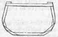
(Centre Mould.)
(Section of Model.)
Fig. 2.
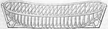
Fig. 3.
(The alternate fore and aft and cross planking.)
Fig.4.
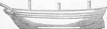
(Profile of the Vessel complete.)
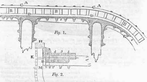
Mr. E. Carey, of Bristol, who has had much experience in ship-building, and has suggested a variety of improvements, recommends the following method of fastening a ship's side, with his newly-invented iron knees, as explained by the subjoined figures. Fig.l. is a horizontal section of a portion of a ship's side and beams; A A shows the ship's side; B B the timbers; C C the thickness of the outside planking, D D a plank, 3 1/2 inches thick, which goes all round the ship, inside the timbers, against which the iron knees are fixed, and bolted through the side; e e an horizontal clamp, 10 inches wide and 6 inches thick, F F the iron knees, 4 inches wide and 2 inches thick, which are bolted through the beams and ship's side, as at G G. Fig. 2 is a section of the same parts as Fig. 1. H is the plank sheer; I the water way; J J the ends of the planks; K a bolt that goes through the ship's side, through the edge of the water way, and six streaks of the deck below the beam, and is clenched on an iron plate on the inner plank; L the arm of the knee; M the ship's timber and side; D is an edge view of the inner plank, as shown at D, Fig. 1. These iron knees and water ways are let down upon the beam 3 inches, and also six of the deck planks, and bolted through also; under the beam a plank, 3 1/2 inches thick, is first brought on, inside the ship, against which the ends of the beam are fixed.
The horizontal clamp, 10 inches wide and 6 inches thick, is then brought on under the edge of the plank, and bolted through the side. On this clamp the beam is dovetailed in, one inch down, and bolted through the end of the beam. A ship fastened in this way, Mr. Carey says, will render it impossible for the side to move; that no wet can possibly get down, and that the ship will thus be kept perfectly dry and sound.
Under the head Dock have been described the usual mechanical arrangements and process for building and repairing ships. In this place we shall add a very ingenious and improved method of bringing up ships upon the ways for the operations of the ship builder. A Committee of Inventions appointed in the year 1827, by the Franklin Institute of Philadelphia, to whom the subject was referred, drew up the following report thereon, which seems to have been dictated by sound judgment and impartiality. "The Committeeof Inventions, to whom have been submitted a model, drawings, and descriptions of the ' Radiating Railways for the repairing of Vessels,' invented by Edward Clark, of New York, civil engineer, report, that they have carefully examined the proposed improvement, and consider the plan as offering great facilities, when it is desirable to have several vessels under repair upon the ways at the same time. Morton's patent slip, which is in use in Scotland, is of sufficient length to contain two or three vessels; but it is evident that whichever was the last hauled up, must be the first launched; and they must, therefore, be frequently repaired in haste, without being allowed that time to dry, which is, in many cases, a point of great importance.
Continue to:
My Books

