Tell Tales For Cisterns
Description
This section is from the book "American Library Edition Of Workshop Receipts", by Ernest Spon. Also available from Amazon: American Library Edition Of Workshop Receipts.
Tell Tales For Cisterns
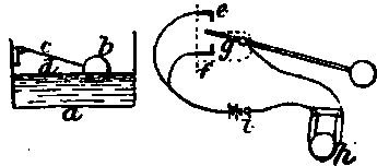
(1) In Fig. 14, a is the tank, b the float, c V-wheels, d light wire rope, e counterbalancing weight (which must be adjusted so as not to prevent the float b falling with the water), f eye (through which the wire rope passer), filed on arm, which, being pivoted at g, is kept against the stop h by spiral spring k until the atop (, fixed on the wire rope, is brought in contact with f by the rising water, when the weight e pulls the arm over to i, which brings the bell into circuit-By moving the stop I, the bell can be caused to ring at any level of the water, and by having another contact at h, and bell, and also a stop on the other side of /, the bell will ring when the tank is empty. When 2 bells are fitted up, the arm most be arranged to remain between the contacts, when not acted upon by the stops on the wire rope. An indicator and scale attached to the weight b will show the height of water in the tank.
Fig. 14.
(2) In Fig. 15, a is the tank, the height of the water being at b; c is a tin float attached to the end of an iron rod d, moving on a hinge at c, f is a metal stud tipped with platinum. A small piece of platinum is also soldered on to the point on the rod d, opposite to f. g is a wooden support to which e and f are fastened. A wire from / is carried to the battery A, which consists of a few Leclanche cells. The other terminal of the battery goes to one of the binding-screws of the electric bell %; the other binding-screw is connected by a wire to e, but care should be taken to have this wire in good metallic connection with the rod d. When the water rises to a certain height, the points at / will be put in contact, which completes the electric circuit and sets the bell ringing. The bell would cost about 4s. or 5s.; the batteries about 3s. each.
Fig.. 15.

(3) In Fig. 16, a is the cistern; b, a float; c, the contact maker; d, a projection to hold float. The right half of the figure shows the contact-maker. e is a brass stud in contact with the line wire and f is another, stud also connected with the same wire, g is a piece of brass spring with the other wire attached to it; h is an electric bell, and i the battery. Platinize all contact points. The action is as follows:-When the cistern is full, the brass spring g touches f, and the bell rings. When the cistern is empty, the springy touches e, and thus completes the circuit. It will be found very useful to employ a switch, so that when the cistern is full, the circuit can be broken, and thus save your battery. The same can be done when it is empty.
Fig. 16.
(4) In Figs. 17,18, 19, the wheel a is actuated by the float, and when revolving, causes the bar carrying the contact-pins to rock on its centre 6, thus producing a circuit on one side or the other by immersing the pins c in the mercury e, the pendulum d bringing the bar into its normal position.. The pins are shown in a line for the sake of clearness, but they can be placed anyhow, so long as they dip together. By using mercury, you will make a great deal better contact than you can with solid metals, but the pins on the bar and the connections must be well insulated. For the recording instrument you will require a couple of ratchet wheels of equal size, but fastened together a little apart, and mounted on a common centre. You must have as many teeth on them as your float-wheel has pins, and the teeth must be cut in an opposite direction to one another, so that when the electro-magnet g attracts the armature and escapement / toward the pole marked S, the wheel at the back revolves in the direction of the arrow (and with it the wheel and index that are shown); the reverse action takes place when armature, etc, is drawn towards N.
Fig. 17.

Fig.. 18.
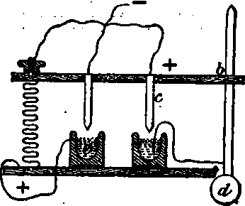
Fig. 19.
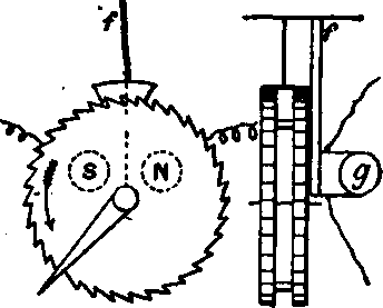
There are several disadvantages in this plan-viz., the necessity of having the batteries at the reservoir, the liability of the instrument to get out of step, and the continuous action if the pins on float-wheel should happen to hold the bar down.
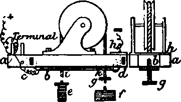
(5) Field & Thompson combine a low-water alarm with an anti-incrustator for steam boilers, as shown in Fig. 20.
Fig. 20.
The current of electricity is caused to pass from the shell of the boiler to a negative electrode situated in the water so long as the level of the water does not fall below a predetermined point; when this level no longer obtains, the current, or a part of it, operates a signal. A dynamo, or other electric generator is provided, and a conductor in connection with the negative pole (that is, the pole which comes from the zinc plate in an ordinary voltaic cell) is passed through the shell or body of the boiler, in such a way that it is electrically insulated. This conductor, which terminates in, or acts as, an electrode, is so arranged that it is normally in connection with the water in the boiler, and by means of friction, part of it is kept clean and bright, so that it may make good electrical connection with the water.
To convey the electric current to the water, and keep the conducting surface or electrode bright, there is fixed to the insulated negative conductor a, at or near the level of the low-water line in the boiler b, a metallic surface, against which c is made to rub, the motion of the latter being derived from some contrivance such as a float d actuated by the motion of the water. The float and nibbing surfaces c are insulated (at the joint e) from the boiler 6, and from the negative conductor a, when not in contact with the submerged clean surfaces /. The float and rubbing surfaces are so arranged that when the level of the water g in the boiler falls below the predetermined point, the rubbing piece c shall not be in contact with the cleaned surface /. Thus all electrical connection between the rubbing surfaces of /, and the negative conductor or electrode a, will be broken, and the electric current through the boiler (whose shell forms part of the circuit) will be stopped. The circuit through the water being broken, the low-water alarm or indicator is brought into operation. A convenient method of indicating this is to cause the current to pass through the coils of an electro-magnet A, which attracts its armature so long as the current flows.
When the circuit is broken, the armature will fall, and the current will be "switched" into the signalling apparatus i, which may he of any suitable construction, such as a trembling hell, or an electric lamp, or an electric motor that will open a steam or water-cock and extinguish the fire.
The drawing shows a trembling hell in conjunction with a plate on the back of the armature, which plate hears the word "stopped," and assumes an attitude in which it is plainly visible when the armature falls, as it does when the current through the boiler ceases. The electric generator may be used in conjunction with a second battery. In cases where the prime mover does not run during the night, a secondary battery is particularly serviceable, as it keeps up the action during the time when there is little or no circulation in the boiler.
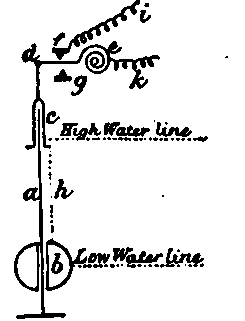
(6) Fig. 21 shows an arrangement for signalling both high and low water levels : a, upright guide-rod firmly fixed to bottom of tank; 6, hollow copper ball, with tube through it to slide over a; c, cap or tube with flange to slide over a at lower end, and attached at top end to d, lever arm mounted on spiral spring e, the centre of which is fixed to a rigid square pin; f g, 2 ends of a brass plate, projecting from a support at right angles to d; h, a light chain, connecting c and b, the length of which regulates the water-levels at which the bell will ring; i k, terminal wires, attached respectively to f and e. At low-water level the weight of b will bring e into contact with g; at high level, its buoyancy will bring e into contact with f.
Fig. 21.
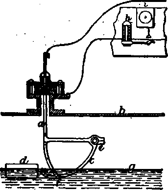
(7) In Fig. 22, a is a wooden frame; b, contact-lever; c, hinge to contactlever; d, brass contact-screw; e, counterweight and stop to prevent weight from passing through lever; f, float; g, stop for same; h, piece of tin for d to contact on; carry wire to contact screw, as shown in sketch, along the lever. When the water gets below a certain point, it would leave the float suspended, which should by the counterweight e lift the contact-lever at i, and make contact at d h. On the contrary, the float f should lift lever at k, and again make contact at b h. To ensure success, the float should be as heavy as possible, the lever as light, and the counterweight heavy enough to lift the lever. The holes in contact-lever should be large enough to clear rope or chain. Pulley should not be less than 5 or 6 in. in diameter.
Fig. 22.
Continue to:
My Books

