Time-Signals
Description
This section is from the book "American Library Edition Of Workshop Receipts", by Ernest Spon. Also available from Amazon: American Library Edition Of Workshop Receipts.
Time-Signals
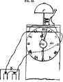
(1) To ring at 6 o'clock. Fig. 23 shows a small clock a, with which to work the bell; b, battery consisting of two Leclanche cells; c, a disc, with a notch cut in it, running out to the diameter of the disc, and having a groove in it in which d, a small piece of wire runs; attached to d is a small strip of sheet copper e, and fixed to it is the gong /. Set the small point in c to the hour required for the alarm to ring, and it will be seen that, when the recess in c works round opposite the hour, the wire d drops down in the recess, bringing with it e, which falls on the two ends of the wire from the battery brought in at the Bides of the clock. The strip e cannot be seen, being above the face. The disc could be fitted to any clock, being nothing mora than a piece of sheet brass with a groove cut in it with a file, to prevent the wire from slipping out. There should be a switch, to torn the current off or stop it. The gong is shown as filed on the top of clock, and battery and clock on mantel-shelf. A common house-bell will do for a gong, supported on a piece of brass wire.
The disc c is of course to be carried by the hour hand.
(2) Have a disc, about 2 in. diam., fastened on to the shaft of the hour-hand, so that it revolves once in 12 hours, and notched about 1/2 in. deep, to allow the pin of contact-rod to drop, and make contact at a b. Divide the disc into 13 equal parts for the hours, and half the spaces for the half-hours, and number them as shown in Fig. 24, when fired, the centre of the hour-hand should always be over the figure 12. Carry the wire from the battery to the contact-rod, as shown, andnot through the joint. This will ring the bell all through the night; but you can switch it off and on, or, if this is unsuitable, make the disc revolve only once in 24 hours, and divide and notch to suit, so that more than one half of disc would be blank. The contact-rod you must shape to circumstances, and make the minute and hour hands coincide.

(3) In Fig. 25, a is a disc of thin sheet brass, with notch cut in it:through the centre is soldered a tin tube to slip tightly on the spindle of the wheel that carries the small baud of the clock, with 2 brass pins soldered on the outer face, just long enough to project through the face of the clock to turn the disc round with. 6 is a piece of brass wire about J in. thick, screwed at one end about 1 in. down, and with 3 nuts fitted; the other part is hammered flat, to form a spring, and filed down to the required stiffness, which of course must not be great. The end that presses on the edge of the disc has a small notch cut in to prevent slipping. c is another brass wire, same thickness as ft, with 3 nuts, and bent as in sketch. Take off the clock face and hands, bore 2 holes through the side of clock-case, one above the disc and the other below, as shown; then by means of 2 nuts fix each wire in position; the other nut serves to connect the wires from battery. All is hidden when the face is put on. A small piece of platinum should be soldered on the spring ft, where it drops on c, also a piece on the end of c to form more perfect connection.
The action is thus: - Suppose 6 o'clock is the time you require to rise in the morning: at 6 o'clock in the evening, turn the disc round by means of the pins until the spring drops into the notch and falls on c; the connection is then made. As the clock moves, the disc raises ft until 6 o'clock A.M., when it drops, and sets the bell ringing. The clock may be in the kitchen, and the wires go through ceiling to bell hanging on wall in bedroom. A simple break is made thus:-Solder a small plate with 2 screw-holes on 3 in. of {-in. brass tube, and nail it to the wall in bedroom; then put a small piece of cork in the bottom of tube, cut one of the wires from battery, file one end to a point, and push it up a short way through the cork; to the other wire, solder 8 in. of gilt picture cord with a brass wire 3 in. long soldered to the other end of picture cord, then pour a small quantity of mercury into the tube. When retiring for the night, merely wind up the clock, and put the brass wire at end of picture cord into the tube, which forms the connection. When the bell rings in the morning, take the wire out of tube, which breaks connection.
Gilt picture cord forms good flexible connections to the clock; solder about 8 in. to end of each wire.
Fig.. 23.

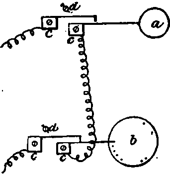
(4) Put 2 pins in the minute-wheel, and let them lift a light spring; this will give a contact-maker every half-hour.. Then a pin on the hour-wheel to suit each hour that a signal is wanted for. Count the teeth, and divide that number by 12, thus, having so many teeth for each hour. Mark one tooth " 12," and at equal distances others " 1," " 2," etc. Miss pins at hours not wanted, and where a half-hour signal is needed, insert a pin half-way between the hours. The arrangement is shown in Fig. 26:a, minute-wheel, with its 2 pins; ft, hour-wheel, with its pins; c, light brass springs, to be lifted by the pins in the wheels; d, adjusting screws. The spring-studs must, of course, be insulated from the clock-plate.
Fig. 26.
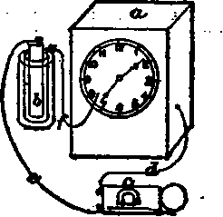
(5) Fig. 27. - a to the clock; ft, battery; c, bell. The wire d from one terminal of the bell is connected with any part of the works behind the clock; the wire e leads from the battery to the other terminal of the bell; and the wire f is placed at whatever hour the bell is wanted to ring. f has a little crook at the end, so that, when the hour hand of the clock touches it, it is carried round with it, the bell continuing to ring till the crook detaches itself by the hand going round-i.e. about 3 hours. / is placed in such a manner that, although the hour hand touches it, the minute hand passes above it. This adjustment, though not so scientific as others, is equally successful.
Fig. 27.
Continue to:
My Books

