Iron Drains. Continued
Description
This section is from the book "Plumbing Practice", by J. Wright Clarke. Also available from Amazon: Modern plumbing practice.
Iron Drains. Continued
There is a little tact required in yarning a joint. Some men will use the yarn just as it is made, no matter whether the socket fits tight or loose; others will take off a strand for a tight joint, or will add a strand - or, if occasion requires, twist two yarns together - for a loose joint, so as to insure the socket being yarned an equal thickness all around. Black or tarred yarn is the best to use, as if any of it comes in contact with water it will not rot so soon. White yarn is best for water-mains, as it does not impart any taste to the water, which the tarred does.
After yarning the joint, a roll of clay is placed around the outside in such a way that when the lead is poured in it projects slightly beyond the face of the iron socket - Figure 168. Sometimes the projecting lead is cut off with a chisel, but this is a mistake. The proper way is to take a hand-chisel and hammer to slightly separate the lead from the pipe, as shown at A, Figure 169, and then a thin calking tool, work it all around keeping it close to the pipe, and then use a thicker tool in the same way. This causes the superfluous lead to bulge outward, as shown at B. A good tradesman will cut this off with his calking tool by its coming in contact with the edge of the socket, and never use a chisel for that purpose, and at the same time will leave the surface of the lead so smooth that the tool-marks can scarcely be seen.
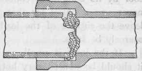
Figure 167.
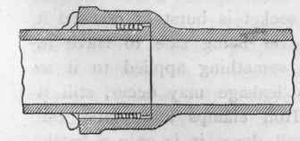
Figure 168.

Figure 169.
If the joint is small, so that it does not require much lead, it should be poured very hot, or it will not run right around, but if the joint is large and requires a good thickness of lead, it should not be made very hot for the reason that the hotter the lead is made the more it expands, and, consequently, the more it shrinks as it cools. Another reason for not having the lead too hot is that it burns the yarn and causes it to smoke, which, bubbling through the lead before it sets, leaves a lot of little cellules in it, through which the water can afterward find a way of escape.
The way to test an iron pipe as to its freedom from cracks or splits is generally to "ring" it with a hammer; if a jarring sound is emitted, it is a certain sign that there is some flaw in it, but if it "rings like a bell" it may be taken for granted that the pipe is in a sound condition. Sometimes a pipelayer will "set up" his joint too much, so as to split the socket or hub, and this is more likely to occur when hard lead is used. Or he will perhaps drive his tool in between the pipe and socket so as to burst it, but a man who is used to the work will at once detect this by the sound. When a socket is burst or cracked it should always be taken out, it never being safe to leave it, and although the crack may have something applied to it so that the iron will rust so that no leakage may occur, still it is always liable to break open. Iron clamps and plates can be bolted on, but no matter how well done, it is only a botch, and the cost is almost equal to that of a new length of pipe. Another test generally insisted upon by engineers is that all pipes for best work shall be not less than the following weights: 3-inch pipes, 1 cwt. o qrs. 14 lbs. the 9 foot 4-inch length.
4 | " | I | " | 2 | " | 0 | " | " | " | " |
5 | " | 2 | " | 0 | " | 0 | " | " | " | " |
6 | " | 2 | " | 2 | " | 0 | " | " | " | " |
7 | " | 3 | " | 0 | " | 0 | " | " | " | " |
It is an open question if these weights should not be modified, as, although the substance may be about equal in all sizes, still the larger pipes should be made thicker in proportion than the smaller ones, as the perimeter of the larger pipes has to resist a greater hydraulic pressure. Another test sometimes insisted upon is that these pipes should withstand a pressure of 400 feet head of water. I was carrying out some iron pipework some few years ago which was tested to this pressure, and there was not one defective pipe found. Two or three joints had to be reset, and that was all in a £4,000 job.
One firm of London plumbers use cast-iron pipes of the following weights:
3-inch pipes, | 45 lbs. | per 6-foot length. | ||
4 | " | 60 | " | " |
4 1/2 | " | 70 | " | " |
5 | ' ' | 82 | " | " |
These weights may do very well for overground work, but I think the heavier pipes are better for underground. The heavy pipes have the further advantage of being made in longer lengths, as well as having stronger sockets to resist the necessary setting up of the joints.
Some makers have a groove inside the socket, as shown at C, Figure 165, but this is not of much advantage, as the socket is generally rough enough inside for the lead to key to.
When cast-iron pipes, coated with Dr. Angus Smith's solution, are used for drainage purposes, they may be buried in the ground without much risk of deterioration by rusting, but it is advisable, in some kinds of soil, to have a concrete bed for them to lie upon. One eminent firm of sanitary engineers makes a concrete bottom to the trench, and then supports the iron drain pipes on small brick piers, and then builds a wall on each side, laying flat stones over, so as to leave a space all around the pipes. This space is continued to the external faces of the house-walls where air-gratings are fixed. By this arrangement a current of air may circulate through from end to end, and all around the outsides of the pipes. Figure 170 is a sectional view showing this arrangement. Another advantage claimed for this system is that the jarring of the floor cannot disturb the pipe drain in any way, and if a light be held at one grating, a person looking through the other can see if any leakage is taking place, It is a further advantage for the iron pipes to lie on horizontal iron bars, as shown by dotted lines, so as to leave the space beneath perfectly clear. In one case iron pipes were fixed in a building which had been erected on virgin ground. These pipes were broken soon afterward by the settlement of the earth outside of the walls, the pipes being built in and held so firmly that they could not move. Figure 171 explains what actually occurred. To avoid this a small relieving arch should be built over all drains (whether iron or vitrified stoneware) when they have to pass through a wall, in the manner shown in Figure 172, so that if the house-walls, or the earth in which the drains are laid, should sink, no strain would be brought to bear on the pipes. In some cases - and they are very few - it is possible to fix the pipes on the house-walls instead of burying them under the floors. No doubt this is a good plan, but in nearly all town houses the basement floor is used as servants' offices, and as these rooms require sinks and other fittings with waste-pipes to them, the drains must of necessity be fixed at a lower level. A speaker at the late Plumbers' Congress, held at the Health Exhibition, advocated a tunnel to be built under houses ranged in rows, through which the drains should be carried. These tunnels were to be large enough for a man to pass through, so as to be able to examine the condition of the pipes. It is doubtful if this would be a good plan. Setting aside the question of cost, in a great many cases these tunnels would be lower than the foundations of the house, and would thus interfere with the stability of the building. Again, where the soil is charged with water from land-springs or other causes, it would ooze through the walls and probably half fill the tunnel.
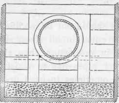
Figure 170.
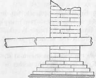
Figure 171.
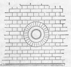
Figure 172.
Continue to:
My Books

