Soil Pipes And Traps. Part 2
Description
This section is from the book "Plumbing Practice", by J. Wright Clarke. Also available from Amazon: Modern plumbing practice.
Soil Pipes And Traps. Part 2
The subject of traps cannot be dismissed without a few remarks on trap fixing. It is admitted by all advanced sanitary engineers that traps are necessary under water-closets and other fittings that require waste pipes. There are some few people who think otherwise, but they are mostly amateurs, and those of limited experience. If we are to accept the dictum that traps are necessary, it follows that they should be fixed in such a way that they are not rendered useless by the way of fixing them. One of the first things to guard against is fixing the traps in such a way that the seal is broken. The writer has several times found traps fixed as shown in sketch section, Figure 391. D-traps, and also the P-traps, have been found to have the seal broken by improper fixing. In some instances this appears to have arisen from branching the trap outgo too low down in the vertical soil pipe when the trap has been pulled up after fixing, so as to be in its proper position for the water-closet. It may also have occurred in another way. If the piece of pipe from the trap to the vertical soil pipe has been cut too short, the P-trap has been strained open and so distorted in shape., in the endeavour to make it longer, that the water-seal is broken, as shown by Figure 391. In other cases the vertical soil pipe has been insufficiently supported, with the result that it has broken away from its fixings, and slid downward, causing the branch pipe to drag down the outgo-end of the trap, thus breaking the water-seal. The straining and bending of traps in their position after fixing is a natural sequence with those men who work by rule of thumb. I will illustrate this: When a plumber is going to fix a trap and soil pipe, he will often stand a length of soil pipe in the position intended for fixing it. He will then place the trap in its position, and take a short piece of soil pipe and cut and rasp the ends to fit between the trap and vertical pipe. The next operation is to remove the whole of the work to the bench in the workshop, when the hole is cut in the vertical pipe, and the necessary soiling and shaving done to the parts intended for soldering. The work is again placed in its position and the parts fitted together. After doing this the joints are " tacked " - that is, some hot solder is splashed on the joints and left until it has set. The work is now again moved to the bench and the joints made. During the operation of making the joints it frequently happens that so soon as the tacking solder is melted, the work will shift and so get out of its proper position. On again moving the piece of work into its position, it will be found not to fit; but lead being a very soft metal, it is easy to "spring" it - that is, bend and strain it - until it suits the intended position.

Figure 389.
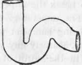
Figure 390.

Figure 391.
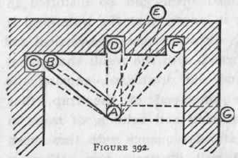
This rule-of-thumb business should be strongly condemned. In the first place, a great deal of time is wasted when moving the work up and down between the shop and the intended position. The shop is generally in the basement, and the work may perhaps be going to be fixed on the third, fourth, fifth, or sixth story of the building, and thus a great deal of the plumber's time is misspent. In spite of all care taken when fitting the work, it frequently happens that it does not "fit" when completed. The proper way of setting out this kind of work is as follows: - Let Figure 392 represent a plan of the opening for a single water-closet. Now water-closets, such as the valve and others, which require a trap beneath them, and which have the outlet in the centre of the apparatus, require the trap to be placed central - that is, equidistant from the side walls. The distance from the back wall is governed by the depth of the water-closet seat. Some architects will have the seats 1 foot 9 inches from back to front, and others specify them to be 2 feet 6 inches, so as to leave more room for the user's dress, and also to leave room for hanging the perforated part of the seat as well as the flap. To take a medium, and the most commonly used, width of seat - say 2 feet - the trap should be fixed with the centre of the inlet-end 1 foot 3 inches from the back wall. To mark out the work, first of all set out full size on the bench or floor the side and back walls, as shown at Figure 392. Find the position of the trap A, and with a pair of compasses describe a 4-inch circle - that being the usual size of the inlet of traps. If the soil pipe is 4 inches, and going to be fixed in the angle as shown at B, describe a similar circle at that point. If the soil pipe is to be 3 1/2 inches in diameter, or any other size, describe a circle equal to the end section of the pipe. If the soil pipe is to be fixed in any of the positions shown by dotted lines at C, D, E, F, G. or any other position, the circle should be made in that position. The next thing is to take a piece of strong lath - say 1 inch thick by 2 inches wide - and cut it to the exact length between the two circles. All the lines can now be rubbed out as being of no further use. The next operation is to set out a pair of parallel lines, as shown at H, J, Figure 393, the distance apart being equal to the diameter of the vertical soil pipe. Now take a long rod and place the bottom end on the drain-socket if it is for the first length, or on the top end of the last length of soil pipe that was fixed, if for an upper floor, and mark on the rod the top of the floor-joist where the trap is going to be fixed. When a rule is used for taking a dimension, a mistake may crop in, but by using a long rod the liability to error is minimized. Now lay the length of soil pipe between the lines H, J, and measure from the bottom end with the rod, allowing half-an-mch for a joint at the bottom end, and transfer the mark of the top of the floor-joist from the rod to the pipe, and also on the setting-out marks, as shown at K, Figure 393. With the small rod that was cut to an exact length, set out the distance K to L. 4 inches away make another mark at M. Between these marks lay the trap so that the crown of the outgo is below the line of the floor-joist. Scribe or mark on the bench the shape of the trap, and draw parallel lines from the trap outgo to the lines representing the vertical soil pipe, giving these lines a declination from the trap, but not allowing them to come below the line N, which represents the bottom edge of the floor-joist. The reason for this being that the pipe would look unsightly if seen below the ceiling. When small soil pipes are used it is necessary to bend the end of the branch soil pipe as shown by dotted lines, for reasons given in an earlier chapter.
Continue to:
My Books

