Soil Pipes And Traps. Part 3
Description
This section is from the book "Plumbing Practice", by J. Wright Clarke. Also available from Amazon: Modern plumbing practice.
Soil Pipes And Traps. Part 3
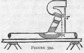
Marks should be made on the long length of pipe at O, O, and then the hole for the branch pipe opened between those marks. The branch pipe can be cut the exact length, and with the end at the proper angle for connecting to the other pipe, and if properly done will not require any rasping or fitting in any way beyond what is necessary to keep the solder from running through when the joint is being made. . The other end of the branch pipe should be cut half-an-inch longer than the mark P, Q, to allow for the outgo of the trap to enter a short distance. As a rule, the joint on the outgo of a P-trap is straight. After soiling and preparing the ends, this joint should be made. The branch joint should then be prepared and placed in position for making, as shown at Figure 394.

Figure 393.
Wood blocks should be fixed inside at R, as described in an earlier chapter, to support the weight of the trap and branch pipe.
The piece of lath that was cut to the exact distance between trap and vertical pipe should be placed as shown at T, Figure 394, to insure that they are the proper distance apart, and should be left there until the branch-joint is made, to prevent the trap falling forward, and also help to support the weight of it. The sides of the pipe laying on the bench should be scotched to prevent its rolling, and a piece of 1-inch pipe bent to a U-shape and laid across the trap, with the ends resting on the bench, will be found to be all that is necessary for fixing the work until the joint is made; or two clout-nails can be driven into the edges of the bench, and a stout piece of string passed round the trap, the ends being fastened to the nails for the same purpose.
Before making the branch-joint, a set square should be placed on the bench-mark K, Figure 394, and should touch the crown of the trap at S. If a D-trap is being fixed, a straight-edge laid on the flat top of the trap should touch the bench-mark, K - that is, if the trap is properly fixed. The above way of setting out traps and soil pipes is not new, it being taught to the writer when he was a lad. If taken as a problem in geometrical projection, it would be set out as Figure 395; the dotted lines being the plan, and the firm lines the elevation.
To show the value to plumbers of a knowledge of drawings, the writer a few years ago had a set of drawings of a house being built at Shanghai, in China, given to him for his guidance, as to the positions of the cisterns, water-closets, sinks, etc. The whole of the work was set out full size on the workshop floor, in London, and made and put together ready for placing in position. Brass unions were soldered on to the pipes where, of necessity, they had to be made in sections for convenience of removal or stowing away in packing-cases. Each part of the work was labelled as to its position, and the unions were all numbered for the guidance of the workmen who fixed them. The whole of the work was found to fit its intended position, and the only hitch was a delay in replacing some marble slabs for wash-hand basins and urinal backs and stalls that got broken in transit from England to China.
Figure 392 represents a plain setting-out for a water-closet trap and soil pipe, but sometimes difficulties present themselves. Figure 396 is an example. In this case the water-closet was fixed on the staircase landing, and so as not to spoil the appearance of the elevation of the house, the window was continued to the top of the stone landing on which the water-closet was fixed. In addition to the bend shown on the plan, Figure 396, another bend was required, as shown by dotted lines, Figure 397, so as to avoid cutting away the skew-back of the brick arch outside and the bearing of the wooden lintel inside.
There are architects who bestow some thought on the* arrangements of water-closets and soil pipes, but they are the exception rather than the rule. The above fittings are generally the last consideration when designing a house, and any small spare space that may be left after forming the rooms is generally appropriated for a water-closet or sink, or something of the kind. Very often no spare space is left, and the result is the water-closets are introduced into all sorts of unsuitable positions, thus presenting all kinds of difficulties for the plumber to overcome. In one case the writer had to make three bends in a short length of branch soil pipe to avoid going through a chimney-flue. In another case five bends had to be made to avoid cutting away the main supports of a floor in the centre of a building. A case occurred where 3 inches were cut out of the top edge of a 9-inch rolled-iron joist, and another where 4 1/2-inch holes had to be cut through the web of a riveted plate-girder. It is unnecessary to describe these details any further, but close this chapter by drawing the reader's attention to Figure 398, which is a fragmental plan showing how the water-closets are arranged in a large hotel in London. A is a shaft in which are fixed all the soil, gas, waste, main, and down service pipes. Also the hot-water circulation pipes; these last being a valuable auxiliary for creating an up-current of air. The water-closet chambers are ventilated into the shaft, and may be said to be fairly free from local smells which are generally found in these places.
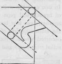
Figure 395.
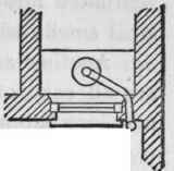
Figure 396.
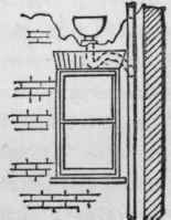
Figure 397.
Another advantage of the above-mentioned shaft is, the pipes are all easy of access for repairs or any other purpose, such as removing stoppages, etc.

Figure 398.
Continue to:
My Books

