Chapter XXXV. Soil Pipes And Traps
Description
This section is from the book "Plumbing Practice", by J. Wright Clarke. Also available from Amazon: Modern plumbing practice.
Chapter XXXV. Soil Pipes And Traps
The commonest kind of trap used a few years ago, and which has been illustrated, written, and spoken about in such a way one would think that the last had gone into the melting-pot never to return, except in another form, is still very frequently used by a certain section of people. The D-trap, Figure 383, is referred to, and it is to be hoped that our lately-organized Plumbers' Registering Committee will keep their books clear of the names of those who advocate its use in preference to all others. Some fourteen or sixteen years ago a plumber, who had advanced ideas, saw some of the evils attached to the D, and designed a trap as illustrated in Figure 384. This was a great improvement, as the scour through this trap kept it much cleaner than the old-fashioned one could be, and, in addition, if the gases emanating from sewage corroded the trap it could be discovered by water leaking out of the holes; whereas, in the D-trap, the dip pipe, being exposed on both sides to the action of the gases, was soon eaten through, and thus rendered the trap useless for keeping smells from escaping. Being out of sight, these holes can very rarely be discovered until the smells become so bad as to lead to the water-closet being taken up for the trap to be examined.
Figure 385 is an illustration of a good old trap. One is shown at the Parkes Museum of Hygiene. The writer has seen a few taken out of a certain locality in London, and as they are not generally met with, it leads to the presumption that they are all the work of one man.

Figure 383.

Figure 384.
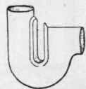
Figure 385.
From appearances one is led to the conclusion that the body of the trap was bossed up and then the throat-piece wiped in afterward.
A friend of the writer's, and a man of great experience, used to make all traps for fixing beneath water-closets as Figure 386. The traps were made in two halves out of sheet-lead, and I have assisted to make them, on iron moulds, and then soldered together afterward by wiping a seam on each side. The inlet and outlet ends were 4 inches, but the body of the trap was made ago, which had pieces of glass fitted to the sides. Although the water-closet over this trap is much used, the accumulation of fur is so very small that a person standing on one side of the trap can see the light of a candle held on the other side. The patentee claims that this trap is proof against momentum, or the water rushing through the trap, as described when alluding to Figure 386, and certainly the trap fulfils the claim.
5 inches in diameter. They were made in this way with the object of reducing the syphonic action that takes place more or less with all unventilated traps when fixed under water-closets, and with a soil pipe attached to the outgo. Another reason was to break the impetus of the water discharged from a water-closet. The impetus given to the water when falling into the trap often being sufficient to carry it right through an ordinary round pipe trap, scarcely any water remaining behind to form the proper seal. In the north of England great numbers of traps are made as shown at Figure 386, but of equal diameter throughout, the seams at the sides being made with fine solder and copper-bit. This seam is not nearly so strong as the wiped one described in Figure 386.
Some years ago commenced a new era in trap-making, when they began to be cast instead of being made by hand. The old patterns, with very little variation, of the D and round pipe P traps were made, and then later on a patent was taken out for casting traps on the principle of that shown at Figure 384. Figure 387 is an illustration of this trap, which is now being superseded by that shown at Figure 388. In Figure 387 the body of the trap is much larger than the inlet, but in Figure 388 the sizes are in reversed order, the waist of the trap being much smaller than the inlet. The inlet is 4 inches, and the body of the trap 3 inches in diameter. Those the writer has fixed have been found to be quite free from fur after two years' usage, and he has seen one, fixed nearly seven years
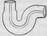
Figure 386.

Figure 387.

Figure 38S.
In addition to cast-lead traps, a great many are being used that are made in the same manner as drawn-lead pipe - that is, the lead is forced through dies which gives it a round section, but by manipulating the press, the pipe, as it issues from the dies, is made to curve round in the desired shape to form traps to use in various positions. To show how much under control is the press for making traps, one kind is shown at Figure 389, which is of one piece, no solder or other means of joining lead together being used. Figure 390 is a trap differently shaped, but made by the same means as the other one. Figure 390 is made especially to the order of a master plumber, who claims that it is proof against momentum.
A great many other examples of traps could be given, but it is quite unnecessary, as they are mostly made on the lines of those that have been described in this and earlier chapters. It may be added, however, that all traps for fixing under water-closets must have a clear waterway through them, and that mechanical traps such as those with hinged flaps or valves, or balls, either floating or heavy, so arranged as to form an effectual seal, cannot very well be used, as paper and other matters that pass through a water-closet would cling round the working parts, and so render them useless. In some cases certain matters would accumulate round the valves, etc, and in time form a complete stoppage.
Continue to:
My Books

