Smith's Tools. Part 5
Description
This section is from the book "Handcraft In Wood And Metal", by John Hooper, Alfred J. Shirley. Also available from Amazon: Handcraft In Wood And Metal.
Smith's Tools. Part 5
(18) Lathe Tool Holder
Used for holding high-speed steel turning tools. As these small tools can be ground on an emery wheel, and the holder takes the strain of the cutting, steel of small section can be used, so saving cost of material and the trouble of forging.
(19) Spring Planisher for finishing off iron and steel. If it springs too much a piece of hardwood is wedged in the hollow.
(20) Three-jawed Chuck fitted on to a face-plate of a lathe. The correct name is a Cushman three-jawed geared scroll chuck. It usually has two sets of jaws: the ones in the chuck are outside jaws.
(21) Inside Jaws
For Cushman scroll chuck. These are all moved simultaneously by means of a key. Used for holding work that has to be turned.
(22) An Independent Four-jawed Chuck, with reversible jaws, slotted for bolts, and has not been fitted to a face-plate. Used for holding irregular shaped pieces of work, parts of which have to be turned. Holds work that (20) cannot hold.
(23) An Archimedean Breast Drill-Stock
Used by hand for light drilling.
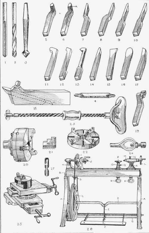
Fig. 22.-Metalworker's tools.
Description of Fig. 22 (continued).
(24) A Lathe Carrier
Used for screwing down on to the end of a piece of work that is being turned between the centres of a lathe. The tail catches on the angle piece in the driving chuck J (26) or the dog in the driver plate. Made in many forms and in cast iron, malleable iron, and steel.
(25) A Compound Slide Rest, bolted to the bed of a lathe. Used for holding turning tools and moving them with precision. The circular piece on top is the tool holder and it can be moved in a circle, and the two set screws hold the tool in position. The top slide moves parallel with the bed of the lathe, but it can also be moved in a circle by loosening two bolts which are underneath the top slide, about 300 each side of a line at right angles to the bed of the lathe. The bottom part of the slide rest is fixed, but the whole of the top portion can be moved at right angles to the bed of the lathe by means of the lower screw. The top slide, which turns on the bottom slide, allows for taper turning.
(26) A Plain Foot-Lathe
It is very simple, and rarely or never gets out of order. With a few accessories a wide range of work can be done with it. It is usually known by the length of the bed B and the height of its centre. That is the height from the face of the lathe bed to the point of the centre in the driving chuck J. The names of the parts are as follows:-
A. Standards or legs of cast iron.
B. Lathe bed. Usually of cast iron with the top and top edges planed smooth and true.
C. Driving-wheel or fly-wheel of cast iron, with vee grooves, for taking a round belt. A fairly heavy one is preferable.
D. Crankshaft. Made of wrought iron, with the ends case-hardened for the conical bearings. The fly-wheel is fixed on to the crankshaft by a key or with a set screw, the end of which goes a little way into the shaft.
E. Crank. Made of wrought iron. Sometimes called the pitman.
F. Treadle. It should be of hardwood and be as wide as convenient, as then it is more comfortable to use. The bolts after being tightened up should have the ends burred, or riveted up; if not, they soon work loose and drop out. The bar at the back to which the treadle supports are riveted, and which works between two centres, is called the treadle shaft.
G. Back stay or stretcher. Made of wrought iron. Keeps the standards rigid and the correct distance apart.
H. Fast headstock. Made of cast iron, the tail end bored with a hole to take the tail screw, the front end bored to take a coned collar of hardened steel.
I. Driving pulley of cast iron. Fitted on to the steel mandrel. Kept in position by being a force fit. Has four grooves for the reception of the gut band.
J. Driving chuck. This screws on to the nose-piece of mandrel and is fitted with a catch bar which is kept in its place by means of a set screw. The centre is kept in position by being a taper fit.
Description of Fig. 22 (continued}.
K. Tailstock or poppet head. Made of cast iron and drilled to receive the barrel M, which is screwed and is made to move backwards and forwards by means of the hand-wheel L. When necessary it is fixed by the set screw N.
L. Hand-wheel of cast iron. This is keyed on to a screw which works in the barrel M, so moving it backwards and forwards.
M. Sliding barrel. Made of wrought iron and screwed for the screw which is fixed to the hand-wheel L. Has a taper fitting at the forward end to take a centre, and has a keyway cut in its length into which a set screw is fitted, so preventing the barrel turning when the hand-wheel is turned.
N. Set screw of wrought iron or steel. Used for fixing the barrel.
O. Tool rest. Made of cast iron. Moves on a base plate, which is fitted to the bed of the lathe. Can be placed in any position.
P. Tee rest. Usually of cast iron, which in consequence generally gets broken. Should be of malleable cast iron or wrought iron. If holes are drilled in the top they add to its convenience.
Q. Set screw of wrought iron or steel. Fixes Tee rest in the correct position.
R. Hand nuts. Made of cast iron. Made like this so that they can be tightened without the use of a lever or spanner. They run up against the cast plates which fit the underneath part of lathe bed; these have a hole in them, through which the bolt passes.
S. Nut and cast plate for tightening up fast headstock.
(27) Hook And Eye
Made of tool steel hardened and tempered to a purple colour and are screwed inside. They are used for connecting the gut belts used on light machinery and foot-lathes. The gut belt is tapered at the end and the hook or eye screwed on until the end of gut comes through; this end is then burnt down level with a red-hot piece of iron. Gut belts can be tightened by twisting them up, or loosened by untwisting them.
Continue to:
My Books

