Pointers And Transoms
Description
This section is from the "The Elements Of Wood Ship Construction" book, by W. H. Curtis. Also see Amazon: The Elements Of Wood Ship Construction.
Pointers And Transoms
Pointers are placed in vessels for two reasons, the first being to furnish additional stiffening to the hull at the locality where the pointer is placed, to aid in resisting panting movements and stresses, and the second, to add additional strength against torsional strains such as are experienced at the ends of a ship when rolling heavily at sea.
There may be from one to three pointers at each end of the ship, depending upon the size of the ship and the designer's ideas. Fig. 98 shows a single bow pointer, and Fig. 99 two stern pointers.
Pointers are set on top of the ceiling. They should be joined together at their lower ends and should extend upward at least to the first deck. At the lower ends, a natural crook hook, or a straight grained crutch is generally fitted, thus tying the two halves of the pointer securely together. Figs. 100 and 101 show characteristic shapes and arrangements of bow and stern pointers.
Where pointers abut deadwood, as in pointer "B," Fig. 99, the crutch, or hook, is sometimes omitted. If fitted, it would in this case, be formed from a straight grained timber and would rest on top of the deadwood.
Pointers may be cut from solid timber, or they may be built up in laminated form as shown in Fig. 104. As the latter form is much the easiest to fit in place and has fully as much strength as the solid type it is coming more generally into common use.
Where the pointers are cut from the solid, molds giving the proper shape, must be lifted from the ship. The method of lifting these molds is shown in Fig. 103 and may be explained as follows:
Since the pointer does not vary in siding its seat upon the ceiling may be scribed by two parallel lines, one even with the upper face of the pointer, and the other even with the lower face, the distance between the two lines representing the sided dimension of the pointer. These two lines are indicated in the figure, as being scribed on the ceiling, but the limitations of drawing prevent showing the ceiling while still maintaining the clearness of the other essential details.
Now, at the upper end fit end cleat "A" against the ceiling and in such position that the edge and corner "C" will set square with the upper and lower faces of the pointer, or, which amounts to the same thing, square with the molds shown in the figure. Then at the lower end fit end cleat "B" so that its edge "C" is parallel to edge "C" of end cleat "A." Fit intermediate cleats sufficiently close together to hold molds in proper position for scribing. It is not necessary that these intermediate cleats be square with the molds, but their upper and lower ends should be in line with the corresponding ends of the end cleats, and each end should land exactly on one of the lines scribed on the ceiling. It will be seen that the length of the cleats will be the same as the sided dimension of the pointer, or the distance between the two lines, and that the upper mold will be held with its lower face even with the line, while the lower mold will be held with its upper face even with the line. Each mold should be scribed on the face that is even with the line.
The molds, which have been previously roughed out to approximate shape, are now set on the cleats and scribed and trimmed until they exactly fit the ceiling. Then with the molds tacked in the position where they fit, scribe the marks shown at edges "C" at cleats "A" and "B" on each mold. Note that there are two marks on each mold at end cleat "A," one for locating the molds longitudinally, and the other for locating the molds laterally. Hence the necessity for setting this cleat square with the molds. At end cleat "B" it is necessary to locate the molds laterally only, hence but one mark is required.
Now, by squaring a line around the timber, corresponding to the upper side of end cleat "A" and gauging another line around the timber lengthwise and corresponding to the edges "C," the workman is enabled to spot the two molds, each on the proper face of the timber and in its proper relative position to the other mold. Thus the outboard face, i. c, the face fitting the ceiling may be marked out and cut. The inboard face of the pointer is scribed or gauged from the outboard face. Very often the pointer is tapered in molding, and where this is done care should be taken to keep the same molded widths at corresponding points on the upper and lower faces. This will keep the inboard face parallel with the ceiling in the vertical direction and gives a nice appearance.
Expert workmen very often fit only the upper mold, in which case the faying face of the jointer is determined by bevels, taken between the mold and the ceiling.
Hooks and crutches are scribed in the same manner as will later be explained for hanging knees.
In fitting pointers it is necessary, after the timber has been worked to proper shape, to spot bore the face that fits the ceiling, in way of all bolt heads, etc.
The operation of fitting the laminated pointers is so simple that no detailed explanation is required, except, perhaps, to remind the workman that the various timbers making up the pointer must be carefully selected for bending. Each course, or lamination, should be well steamed and sprung into place while hot. It is necessary also to fasten each course with boat spikes as it is sprung in place. These are generally driven in way of the frame bays so that the frame space will be kept clear for the through fastening, which is not driven until all of the laminations are in place.
The bolted, or through, fastening is generally the same for solid or laminated pointers and usually consists of four-headed blunt bolts at each frame, all driven from the outside and clinched over rings on the inside. These, of course, like ceiling bolts are driven before the planking is put on. Additional fastening is provided in way of the hook or crutch, this being in much the same proportion and arrangement as that described later for hanging knees.
Where the clamp arrangement is such as to permit, the upper ends of the pointers are sometimes landed against a beam, to which they are connected by a root, or natural crook, knee.
Transoms are generally located as shown in Fig. 99, though they may be fitted abaft the rudder post as well as the stern, or propeller post. They are usually built up on top of the ceiling and are located where they will best correct the deficiency of thwartship strength in way of the half frames or cants. A typical shape for the transom is shown in Fig. 102 and it will be noted that it is built up solid like a small bulkhead. Transoms are thoroughly bolted through the ceiling into the frame, a large proportion of the bolts being generally driven from the outside and clinched over rings on the inside. They should also be well bolted into the stern or rudder post, to whichever they happen to be fitted.
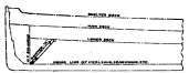
Figure 98. Pointers And Transoms.
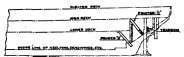
Figure 99. General Shape Of Pointers.

Figure 100.

Figure 101.
Figure 102. Genebal Shape Of Transom.
Continue to:
My Books

