Lathe Equipment
Description
This section is from the book "Machine Shop Work", by Frederick W. Turner, Oscar E. Perrigo, Howard P. Fairfield. Also available from Amazon: Machine shop work.
Lathe Equipment
Setting Up Change-Gears for Thread-Cutting. The descriptions in the preceding pages apply particularly to the usual form of engine lathe, and a clear understanding of its construction and the details of its essential parts is desirable. Instead of being placed directly on the main spindle, the first gear J of the train of "change-gears" used for driving the lead-screw 0 for thread-cutting, is fixed to the stud shaft H, shown at B in the diagram, Fig. 97, upon the inner end of which is fixed the stud shaft gear 6r, which engages a gear F of the same diameter fixed to the main spindle at the left of the cone pinion D. By this means the stud shaft H rotates at exactly the same speed as the main spindle. The small feed-cone I is fixed to the stud shaft H, and the large feed-cone K to the feed-rod N, by which ordinary turning feeds are produced.
Referring to the end elevation A in Fig. 97, the change-gears J and L being of equal diameters and equal numbers of teeth, it follows that the lead-screw 0 will revolve at the same rate as the main spindle. Therefore, if the lead-screw is cut with four threads per inch, the lathe carriage will move a quarter of an inch at each revolution, and the lathe will cut four threads per inch.
The intermediate gear M does not change the rate of speed, although it reverses the direction of revolution.
If the change-gear J is only one-half the diameter of the change-gear L, the lead-screw 0 will revolve only one-half as fast as the main spindle, and therefore the lathe will cut eight threads per inch; but if the case is reversed and the change-gear L is only half the diameter of the change-gear J, the carriage will move twice as fast as in the first instance, and the lathe will cut two threads per inch. From this condition we deduce the rule:
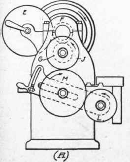

Fig. 97. End and Front Elevation of Engine Lathe for Thread Cutting.
The thread to fa cut will bear the same ratio to that of the lead-screw, as the two change-gears bear to each other.
The ratio will be the same whichever change-gear is the larger. It must be remembered, however, that if the change-gear on the stud shaft is the larger, the resultant thread will be coarser than the lead-screw, and vice versa.
To cut any desired number of threads per inch, we first find the ratio which the desired number of threads bears to the number of threads on the lead-screw, and then select such change-gears as bear this ratio to each other.
The gears will revolve in the directions shown by the arrows; therefore the lead-screw revolves in the direction opposite to the main spindle, so that with a right-hand thread on the lead-screw 0 (the usual arrangement), the lathe, geared as here shown, will cut left-hand threads. If right-hand threads are desired, the intermediate gear M is moved to the left, and another gear introduced between it and the gear L. The usual type of engine lathe is therefore provided with an auxiliary set of gearing for the purpose of reversing the rotation of the stud shaft H. These auxiliary gears are known as tumbler gears.

Fig. 98. Compounding Gears.
Continue to:
My Books

