Layout for Planer and Milling Machine
Description
This section is from the book "Machine Shop Work", by Frederick W. Turner, Oscar E. Perrigo, Howard P. Fairfield. Also available from Amazon: Machine shop work.
Layout for Planer and Milling Machine
In laying out the work for the planer and milling machine, great care must be exercised.
It is necessary that there should be a base line to which the lines may be referred. It depends on the character of the work as to how this should be done. Sometimes it is quite sufficient to lay off the base line parallel to one side of the casting or forging. If the side thus used is to be finished, then the base line should be located at the proper distance from it to allow for the finishing. The amount required varies with the character of the casting or forging; this has been fully explained. Usually there is some outline of the rough piece that will serve as a guide.
As an example of the laying-out of work, take the valve and steam-chest seats shown in Figs. 251 and 252. The work is to be machined on a planer. The cylinder has probably been bored. It is then placed on the planer, and so set that the center line through the cylinder is parallel to the platen of the planer. The first machine work to be done is the taking-off of the roughing cut from the face A. This face is to be planed down to a certain height above the cylinder center; this height may be marked on the edge of the valve-seat by the prickpunch mark B. If the surface C is to be planed at the same time, its height is indicated by the prickpunch mark D. These points may be located by means of the surface gage. Set the gage on the platen, and elevate the point to the proper height. Move it so that it will touch the side of the casting at the proper point, and make the marks B and D accordingly. When the surfaces A and C have received the roughing cut, the plan may be laid off as in Fig. 252. With a square having a suitable length of blade, locate the points G and H directly over the center of the cylinder. Cover the surfaces A and C with chalk where lines are to be drawn. Draw the lines I, J, K, and L on the surface A, between G and H. Through the center of the side of the exhaust port, draw the lines E and F at right angles to G H. This is done with a scriber. Lay off half the width of the exhaust port on either side of E and F, and draw the lines M N and OP parallel to E and F. In like manner, draw the lines QR and S T for the limits of the steam ports. All of these lines are to be emphasized by the use of prickpunch marks as indicated.

Fig. 251. Laying Out Valve Seats.
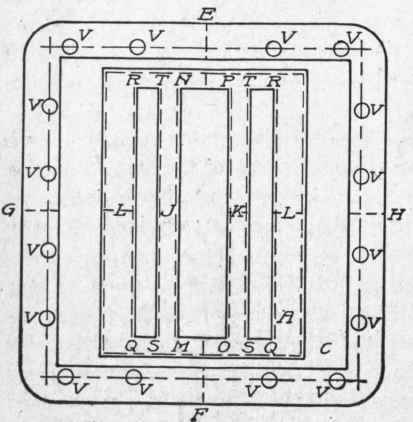
Fig. 252. Layout of Steam Ports.
If the sides of the valve-seat are to be finished, the line to which the metal is to be cut is indicated in the same manner. Finally, the holes VVV, etc., for the holding-down studs of the steam chest, are to be laid out. The center lines are first drawn; then the centers of the holes are marked, after which the circles for the holes are drawn as already described.
Continue to:
My Books

