Cylinders And Hot-Water Circulation. Part 2
Description
This section is from the book "Plumbing Practice", by J. Wright Clarke. Also available from Amazon: Modern plumbing practice.
Cylinders And Hot-Water Circulation. Part 2
Figure 440 is a section of a joint made as described. The pipe ends were passed through gun-metal linings and tafted or flanged over. These linings had hexagonal ends at R, R, and spanners were used for screwing them into the socket, S. T is an asbestos or indiarubber washer, but if the flanged ends of the pipe are properly done and left with a smooth face, they can be butted together and screwed up so as to be water-tight without any washers. These joints require periodical examination and further screwing up, especially when the pipes are in long straight lengths. Horizontal pipes should always lie on wooden fillets fixed to the wall. If fixed on hooks the pipe will bag down between the fixings. The wooden fillet should be rather wide. Although it does not add to the appearance of the work, it is best not to have the pipes too straight so that they will have a direct strain on the screwed coupling connections, but any bends in horizontal pipes must lay flat on the fillet, or air will accumulate in any high parts. When pipes are quite straight the joints leak by the alternate pull and thrust motion which is continually taking place at each change of temperature of the water inside them. It is often lost sight of, but a fact nevertheless, that hot-water pipes when in use are always in motion, and cannot be said to be still for more than a few seconds at a time.
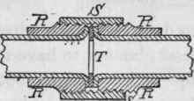
Figure 440.
Great care should be taken when making branch connections for draw-off pipes. Figure 441 is a section showing the T-union used for a branch pipe. It is a good plan not to have the branch pipe quite straight, but to bend it as shown, so as to allow for a slight motion of both the main and branch pipes, and thus render the liability of a strain on the joint to a minimum. In some cases the writer has fixed the branch joint upwards as shown at Figure 442, so as to allow for the motion predescribed.
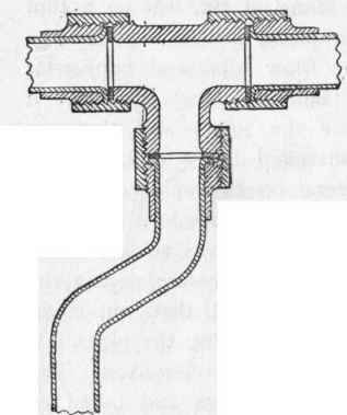
Figure 441.
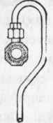
Figure 442.
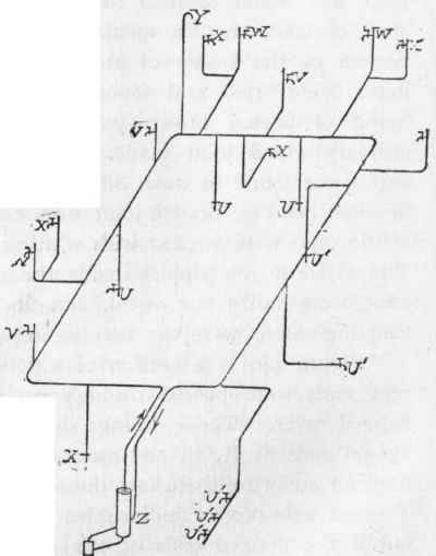
Figure 443.
Figure 443 is a bird's-eye view of a cylinder and the circulating pipes fixed to a nobleman's mansion in the country (England). The whole of the pipes were lead-encased tin. U, U, were draw-offs to sinks on the ground floor. V, V, were similar draw-offs on the first or chamber floor. W, W, were baths. X, X, were wash-hand basins, and Y was the expansion pipe. This was placed at the highest point of the circulating pipe. Doorways and similar obstacles compelled this to be fixed where shown. The return pipe was taken back and branched into the cylinder, as shown at Z. This, no doubt, caused a slight check on the circulation of the water, but it was deemed advisable to make the connection as shown. It was thought that by reason of the long length of pipe and the consequent friction of the water passing through that any water drawn at the cocks, U', U', would most likely be cold instead of hot if it had been connected in the usual way.
Sometimes, as an economy, the return circulation pipe has been of a smaller size than the flow pipe. For instance, a 1 1/4-inch flow pipe has been fixed from the cylinder to the furthest point away, and an inch pipe carried back to the cylinder. This is not a good plan, as reducing the size of the pipe causes, by the extra friction of the smaller pipe, a sluggish circulation of the hot water. In addition to the extra friction of the water in the smaller pipe, there is also, proportionately, a larger radiating surface and consequent loss of heat, so that for these reasons it is advisable to have the circulating pipes of the same bore throughout. Another view of a small return pipe may be mentioned - viz., the smaller the pipe the larger, proportionately, is the radiating surface, so that the temperature of the return-water is much more reduced, and, theoretically, this ought to cause the water to circulate more freely.

Figure 444.
In some cases the hot-water cylinders are fixed horizontal instead of vertical.
Figure 444 is a sketch diagram of a horizontal cylinder and the circulation pipes, as recently fixed under the supervision of the writer. In the sketch, A is the cylinder fixed on brackets over a doorway; B is the boiler; C, C, C, are taps over the scullery, servants' hall, and butler's pantry sinks; d, d, are taps over lavatories; e is fixed to supply hot water to the housemaid's sink on chamber floor, and f to the spray and plunge bath; g is a coil for heating the bathroom, and is arranged so that towels, etc, can be dried or warmed; h is a coil on upper floor to warm a water-closet room and adjacent lobby. The waste heat is made use of by carrying the return pipe through the housekeeper's room and the linen-room, the pipe being bent to form a radiator, as shown at j. It will be noticed that all the draw-off taps are branched into the flow pipe, which is carried as direct as possible, and the coils or radiators are connected beyond the furthest tap so that the water may be drawn as hot as possible at the taps. The coils are so attached to the circulating pipes that by closing three or four stop-cocks the water will flow round without passing through the coils, heat not being wanted in the rooms in the summer time. K is the cold-water supply-tank, and the service to the boiler is shown by dotted lines. The whole arrangement works very well. In this, and similar cases, it was found that after drawing sufficient hot water for a bath the heat from the coils fell considerably, and some little time had to elapse before they got hot again. For this reason it is an open question if the pipes, etc, for supplying hot water to sinks, etc, and also for heating corridors or rooms by radiators is a good one, as it is almost impossible to keep one constant heat.
Continue to:
My Books

