Cylinders And Hot-Water Circulation. Part 4
Description
This section is from the book "Plumbing Practice", by J. Wright Clarke. Also available from Amazon: Modern plumbing practice.
Cylinders And Hot-Water Circulation. Part 4
Figure 450 is, I think, an American invention, and appears to be a simple and easily-applied expansion-socket, but not having used them the writer does not know how long they will last without breaking. But perhaps they are made of very tough but flexible iron, and are as strong as the other parts of the fittings. In addition to expansion-joints it is important that the circulation pipes should not be fixed by any branches, but this was referred to when writing on lead-encased tin pipes.
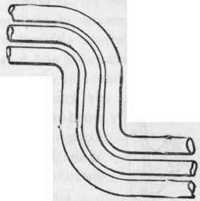
Figure 447.

Figure 44b.
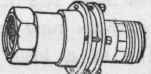
Figure 449.
Figure 450.
When hot-water pipes are fixed round and inside a room, they should not be too tightly fixed at the return-ends, but should be kept at least one inch clear of the walls. Figure 451 explains what is meant, the dotted lines showing how the pipes will bulge out in the centre portion when expanded by heat. If the pipes are fixed clear of walls, as suggested, this would not occur, as the expansion would be expended at the ends. Neither should the pipes be too rigidly fixed by means of wall-hooks. Horizontal pipes should lay on brackets, which, although supporting, will not prevent them freely moving backwards and forwards. Lead pipes should lay on wood fillets, as stated in an earrlier chapter. Figure 452 is a neat brass or gun-metal bracket which can be screwed to a wooden block or lining-board fixed to the walls. Long vertical pipes should be supported in the centre of the length, so that the expansion may be equally distributed at the ends.
To carry out hot-water work in a thoroughly efficient manner, a man requires to know all the principles which govern his work. If he does not know these principles he is always liable to blunder in the arrangement of the fittings and pipes. A man may be a good tradesman, and fix new work that will answer first-class, and yet very often be at a loss to know how to alter other work that has been improperly done by someone else.
Figure 453 is an illustration of a job near Regent's Park, in London. A is a 1/2-inch expansion pipe; B, a 3/4-inch flow pipe; C, a 1/2-inch return pipe; D, a 30-gallon cylinder; E, a 3/4-inch draw-off pipe; F, a 1/2-inch cold-water feed pipe; and G, a small feed-cistern with a 3/8-inch ball-valve. The top of the feed-cistern was fixed nearly level with the top of cylinder. The talented expert who arranged this work was ignominiously dismissed, and another man was called in who spent several days in altering the work, but still could not see how it was that no water could be drawn at the cock, H.
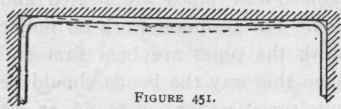
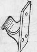
Figure 452.
Eventually he fixed another expansion or vent pipe, as shown by dotted lines at I, when he succeeded in getting a small dribble of water at the bibb-cock. A large fire had been kept up, with the result that sometimes the water was forced out of the feed-cistern and steam drawn at the bibb-cock when opened. This was before the second expansion pipe was fixed.
The second man having been sent away, the owner thought perhaps it would be an advantage to go to a respectable firm of engineers, instead of employing cheap men who knew nothing about the principles which govern the work. He was very much surprised when he was told that the whole of the pipes would have to be changed to a larger size and differently arranged.
Figure 454 shows the alterations, which may be enumerated as follows: The pipe leading to the draw-off cock was branched into the flow pipe from the boiler to the cylinder. The pipes between boiler and cylinder were made 1 inch in diameter. The expansion or vent pipe was fixed from the top of the cylinder, and the feed-cistern was fixed at a higher level. A larger service pipe and ball-valve were fixed, and also a larger pipe from the feed-cistern to the bottom of the cylinder. A damper was also fixed in the boiler-flue so as to regulate the draught. On being told that there was plenty of hot water and enough to supply a bath, the gentleman was so pleased that he had one fixed in an adjoining room.
Figure 455 is an illustration of another blunder which was, if possible, worse than the last one described. This was fitted up in a nobleman's mansion in London by a village blacksmith, in whom his lordship had so much confidence that he paid railway and other expenses sooner than trust to anyone in London. The strange part about this arrangement is, that the water in the cistern, K, did sometimes get hot, but was never to be depended upon for heating. At times it was found necessary to open the cock, L, as air would accumulate in the horizontal pipe, M. The only alteration made in this case was to fix a vent pipe as shown by dotted lines at N, and connect the return pipe from the hot-water cistern to the boiler as shown by dotted lines at O.
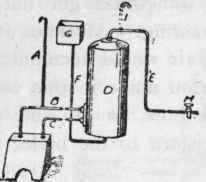
Figure 453.
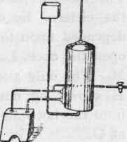
Figure 454.
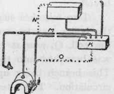
Figure 455.
Continue to:
My Books

