Construction Problems. Part 5
Description
This section is from the book "Shop Projects Based On Community Problems", by Myron G. Burton. Also available from Amazon: Shop Projects Based on Community Problems.
Construction Problems. Part 5
Problem M -Supplementary Problems
To draw a line tangent to a circle at a given point on the circumference.
With O as a center and any radius draw a circle; let P be the given point on the circumference. Join point P with the center O; through point P draw a line AP perpendicular to OP. This is the required tangent. Problem N -
To draw angles of given number of degrees by use of the triangles.
Draw a semi-circle and by using the 45-degree and the 30-degree triangles divide it into angles of 15 degrees. Use your triangles in various combinations and draw as many different angles as you can. Problem O -
Draw a right angle triangle with the altitude equal to the base; this forms what is known as a half-pitch angle, or cut-in rafter or brace construction (Chapter II, Paragraph 24, and Chapter V, Paragraph 75).
Draw a right angle triangle with the altitude equal to two-thirds of the base; this forms the third pitch cut (Chapter II, Paragraph 25, and Chapter V, Paragraph 76).
Draw a right angle triangle with the altitude equal to one-half of the base; this forms the quarter-pitch cut (Chapter II, Paragraph 26, and Chapter V, Paragraph 77).
Problem P - Shop method of drawing an ellipse (with a string) when the two diameters are given.
Draw the longer diameter AB, at its middle point O draw the shorter diameter CD perpendicular to AB; make OC equal to OD. (The lines must cross at the middle point in each.)
With the compasses set to a radius equal to OA, using C as a center, draw arcs cutting AB in points X and Y.
Drive a small brad in point X, and another in point Y, another might be temporarily driven in point C; tie a string around the three brads; remove the brad from point C, insert the point of a lead pencil and swing it around, thus drawing the required ellipse.
Explanation Of Projection Drawing
You have already been told that in shop drawings we use three views, the plan which represents the appearance of the object as seen from above; the front elevation, its appearance as seen from straight in front; and the end elevation, as seen from the right end.
At first it may seem a little difficult to understand these views. A careful study of Plate V will make the matter clear. In the upper half of this plate you will see a perspective drawing of a bracket shelf, represented as though it were surrounded by a glass box. On the top side, marked plan, you will see a drawing representing the portion of the bracket shelf which would appear on this piece of glass, if the parts directly below were projected upon it; the dotted lines represent the underneath parts. On the front side, marked front elevation, you will see a representation of the front of the bracket shelf projected. On the end, marked end elevation, there is a representation of the end of the bracket shelf projected.
If the top portion of the imaginary glass box should be raised, as though it were hinged on the line AB, and the end portion were opened as though it were hinged on the line BD, the three drawings would stand in the positions shown on the lower half of this plate. This explains how the three regular views of any article are made, and just how they should be arranged on the paper.
If the left end of an article is entirely different to the right, another end elevation would be given showing the detail of the left end. If the second end is not shown it is always understood to be identical with the end elevation which is shown.
For further practice in mechanical drawing, you should make practical application of all of the principles which you have learned, by constructing regular three-view drawings of the articles which you are to make in the shop. Further problems dealing with the subject of shop drawings are not given here, because any of the lessons presented throughout the text may be used as models and types, for development of as many plates dealing with shop problems as the time of the class and the inclination of the teacher may direct.
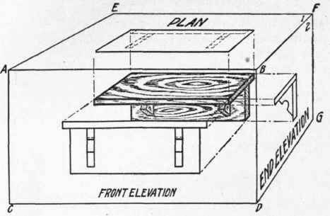
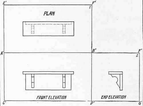
Plate.V.
Continue to:
My Books

