Locating Holes For Bushings. Approximate Methods
Description
This section is from the book "Modern Shop Practice", by Howard Monroe Raymond. Also available from Amazon: Modern Shop Practice.
Locating Holes For Bushings. Approximate Methods
When making any of these styles of jigs, the holes to contain the bushing may be located by several methods.
First Method
If extremely accurate work is not necessary, a templet may be made, or a model piece used having the holes properly located; this piece is placed in the jig and, by means of drills, the holes are transferred to the jig. If the bushings are to be used, the holes may be enlarged by a counterbore having a pilot which fits the drilled hole, and a body of the desired size of the bushing. While this method is cheap, and good enough for certain classes of work, it is not advisable to use it for a really accurate job.

Fig. 260. Jig with Pin and Screw.

Fig. 261. Jig with Cam and Pins.
Second Method
Another inexpensive method which insures fair results is to drill the holes as described above, and then to run a drill or reamer, a trifle larger than the holes in the templet, through the holes in the jig. Then the templet is placed in position, and, by means of a counterbore having a pilot which fits the hole in the templet, the jig is counterbored to the templet, Fig. 262. Better results will be obtained if the ends of the teeth of the counterbore are made of the shape shown in Fig. 263, especially if the drilled hole has run from its proper location.
At times, it is advisable to use a hollow counterbore, Fig. 264. A pin having one end a pressing fit in the hole in the model, and the opposite end a nice running fit in the hole in the counterbore, is pressed into the model. The hollow counterbore, being guided by this pin, cuts the bushing hole to size. The results obtained by this method are about equal to those obtained by the previous one.
Third Method
A third method is used when the bushing holes must be located by measurement, or when there is no templet or model piece. By means of a surface gage, having the point of the needle set at the proper height from a scale attached to an angle iron, Fig. 265, a dimension line is scratched on the surface which has been colored with blue vitriol. The needle is first set to the height of the locating rib. The scale attached to the angle iron is adjusted so that the needle is at the exact height of one of the inch lines, if possible; if not, at one of the half-inch or quarter-inch lines. The needle can then be raised to locate the center of the first hole, and a line scratched while the jig is on edge. The centers of the other holes are now laid off on this plane, after which the jig is turned one-quarter of the way around to locate the hole from the other measurements; where the lines intersect, the surface of the jig should be prickpunched. For this work, the center punch made for centering work to be turned in the lathe, must not be used, but rather the prickpunch, which should be much lighter than the ordinary center punch, Fig. 266. In order that the point may be perfectly round, the point of the prickpunch should be ground in some form of grinder, in which it can be held and revolved. If this is not done, it will be impossible to get the point of the center indicator to run true when attempting to true the jig on the faceplate of the lathe.
Fig. 262. Counterboring the Jig.
Fig. 263. Special Counterbore for Jig.

Fig. 205. Locating Holes with Templet.
While the method just described might be properly classed as an approximate measurement, an experienced workman can locate the bushings within a small limit of variation. More accurate work will result if the height gage is used in laying off the dimension lines. The bottom surface of the extension is set to the height of the locating rib, as shown in Fig. 267; then, by means of the vernier, it can be raised to the exact height of the dimension desired, and the line scribed by means of the point of the extension. This method, although it insures greater accuracy in laying off dimension lines, and is sufficiently exact for most work, is open to the objection that the tool-maker may change the location of centers somewhat when prickpunching.

Fig. 266. Typical Prickpunch and Center Punch.

Fig. 267. Use of Vernier Height Gage for Accurate Location of Jig.
Exact Method
When precise measurements are desired, many tool-makers determine the location of bushing holes by means of hardened discs or buttons. A very common size, Fig. 268, is 1/2 inch in diameter, 3/16 inch thick, and has a 1/4-inch hole. While it is not essential that the diameter be any particular size, it must be some fraction divisible by two without a remainder, as one-half the size of the disc is considered in all computations. If the disc is .500 inch in diameter, .250 inch is the decimal to be considered; but if the disc were ft (.5625) inch in diameter, it would be necessary to consider the decimal .28125 in all computations. In locating the disc, most of the measurements are made with the vernier caliper, and as the tool is not graduated to read closer than .001 inch, it would be impossible to take into account the fractions of a thousandth of an inch; consequently, discs .500 inch in diameter are generally used. The locations of the different holes are laid off by means of the surface gage, the needle being set to the scale fastened to an angle iron, as already described. The holes are drilled and tapped for screws somewhat smaller than the holes in the discs, and the discs are attached to the jig by means of screws. As the screws do not fill the holes in the discs, they may be moved until properly located.

Fig. 268. Hardened Discs or Buttons.
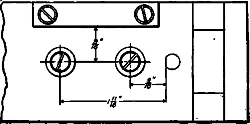
Fig. 269. Jigs with Discs Located from Stops.
Fig. 269 shows a jig having the discs located in relation to the stops.
After properly locating a disc at each point where a bushing is desired, the jig is fastened to the faceplate of the lathe. The jig must be so located on the faceplate that one of the discs will run perfectly true. This can be determined by a test indicator operating on the outside of a button, as shown in Fig. 270. After the disc has been so located, it can be removed and the hole bored to the required size. The jig can now be moved to bring another disc to the proper location, after which it is removed and the hole bored; this operation is repeated until all the bushing holes are bored.
Continue to:
My Books

