Chapter XXI. Drain-Ventilation - Continued
Description
This section is from the book "Plumbing Practice", by J. Wright Clarke. Also available from Amazon: Modern plumbing practice.
Chapter XXI. Drain-Ventilation - Continued
There is such a variety of houses, and they are so arranged, that the drains nearly always have to be treated differently in the way they are ventilated. The greatest trouble arises when an old house has to be redrained; with new ones the necessary provision can be made when building.
Figure 202 is a plan of the front part of a common description of terrace house, and Figure 203 a section on A, B, drawn to a slightly larger scale. In this case the drain, C, from back part of house has to pass beneath the kitchen floor and through the scullery (which is partly situated beneath the sidewalk of the street). The manhole, D, must of necessity be inside the house beneath the scullery floor, and as these places must be perfectly air-tight when so situated, and yet easy of access, a removable cover is placed over the top. Sometimes this cover is of stone bedded in mortar. Some architects specify it to be bedded in putty and white lead mixed together, but these are both bad plans, as the joint cannot be guaranteed air-tight, and if disturbed for any purpose proper care is not always bestowed when refixing. It is much better to use an air-tight iron cover. There are several kinds of these in the market; those are best that are hinged in an iron frame and which can be locked. Those which are not hinged and locked are untrustworthy. Curiosity sometimes leads people to see what is below, and the cover does not always get properly replaced. In one instance three empty wine bottles were found hidden away in the manhole, and that leads to the conclusion that these places could be made use of for other improper purposes unless properly secured.

Figure 202.
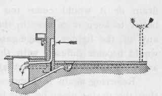
Figure 203.
In Figures 202 and 203, the fresh-air inlet is shown as a branch drain leading through the outer wall where an upright straight-barred grating is placed for air to enter. In this case the grating should be not less than 9 or 12 inches above the area paving, so that dirty water cannot run into it off the surface, or, when the paving is being washed down, cannot be thrown or swept into it. The reasons for this were given in an earlier chapter. This air drain should have a slight inclination, so that should any vapour condense in it the water would run back into the manhole. Too much fall should not be given to this air drain or it would come too low down in the manhole. It is better to keep it as near to the top as convenient, so that should any of the lighter sewage-gases accumulate at that point, they would become diffused with the incoming air and so get carried away up the drain and ventilation upcast pipes.
Referring again to Figures 202 and 203, it should be stated that the drains must be well laid and flushed, or, at times, smells will issue outward through the grating when any discharges are sent down the drains. When iron drains have been laid I never knew anything offensive to pass outward through an open grating, and I have sometimes seen and used them to stoneware-pipe drains. In the case of drains badly flushed or improperly laid, the air drains have to be continued further away, as shown by dotted lines, and a pipe carried up 6 feet above the paving of area, and on the top fix a balanced mica valve in a metal box. Figure 204 is a sketch of this valve and box. The valve is shown by dotted lines, and partly open, as when air is entering.
At Figure 203 the air-inlet is shown by a thick line connected to the drain from the surface-gulley in the area. This is a good plan, as the accumulation of foul air in the branch drain is prevented. This drain can be connected to the manhole, as shown in section, Figure 205. By this arrangement the dirty water from the area gulley-trap is conveyed down to the bottom of the inspection-chamber so as to avoid the walls being splashed, and at the same time the incoming current of fresh air would be divided, part escaping out of the top of the T-pipe, as shown by the arrow, and the other falling to the bottom by reason of its heavier weight, and also to take the place of that passing along the drain and up the ventilation pipe.
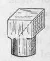
Flgure. 204.
To give the details of the whole of the various means for ingress of fresh air to drains would occupy too much space and time. We will now refer to a few places where the application of those described has been difficult. Figure 206 is a small section showing the application to a row of new houses near Belgravia. In these cases the servants' water-closets were fixed in a front vault under the public sidewalk. An air-grating was let into a shaft carried up to the paving level so as to ventilate the water-closet, and a 4-inch pipe was carried up from the manhole to the under side of the grating, with one of the mica valves, pre-described, on the top end, so that no unpleasant odour should escape to the annoyance of pedestrians. These soon became covered with street driftings, and it was found necessary to make alterations and shield them, as shown at A. These answer very well when proper attention has been given to them by removing the matters which accumulate over the inlets.
Another principle is shown in section, Figure 207. Here the front area is covered in with thick glass and all the front vaults under the sidewalks are used for storing coal. The coal-shoots could not be used for the purpose, so the only available way was to bring back a pipe from the manhole to the main wall of the building, and then up above the covered-in area to a position a few inches above the sidewalk. A cast-iron grating was placed flush with the face of the wall to protect the valve from injury, and behind the grating louvred baffle-plates to intercept dust and road refuse as much as possible from drifting into the mica valve. In the above case the manhole was covered in with a cast-iron air-tight cover, fixed a few inches below the paving. Over this was laid a strong stone slab bedded on dry sand, so that coals falling on it cannot injure the cast-iron cover.
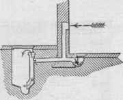
Figure 205.
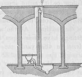
Figure 206.
Continue to:
My Books

