Drain-Ventilation - Continued. Continued
Description
This section is from the book "Plumbing Practice", by J. Wright Clarke. Also available from Amazon: Modern plumbing practice.
Drain-Ventilation - Continued. Continued
Figure 208 is a basement plan showing the drains of a house. Being a corner house, there is only a very small yard at the rear of the building. All the water-closets and other upstairs sanitary fittings have their pipes brought down and connected with the drain in this yard, the drain from this point being laid in a straight line to the public sewer. A disconnecting trap inserted and a manhole built over it, as shown, with an air-inlet arranged at the manhole, and the two soil pipes continued full size to the roof, the system would have worked first-class; but, on referring to the plan, it will be seen that by far the greatest length of drainage is the branch continued to take the waste from the scullery sink and a continuation to the side area for surface water off the paving. It was proposed, in the first instance, to take a ventilation pipe from the head of this drain to the roof, but the owner objected to a pipe (which he said would be unsightly) being fixed up the front of the house. The best suggestion that next offered itself was to fix an air-inlet valve at this point. This was done, but it was found to be always closed, excepting when discharges were sent down the scullery sink, when it would open slightly for a few seconds and then close again, doubtless by the rarefied air in the drain pressing against the back side of the valve. After several experiments it was found that when the airinlet at the manhole was reduced to one-third of its area, which was about 13 square inches, the one in the side area remained open, showing that a current of air was passing through the whole of the system. As this branch drain had nothing but small discharges of water sent down, and which were not sufficient to scour it clean, it was deemed advisable to fix a "Field's" flushing-tank in the scullery (where the frost would not affect it), and a connection was made with the surface water-trap in the side area. This would scour the drain, recharge the trap with water should any evaporate, and also change the water in the trap should it become offensive. The "Field's" flushing-tank was supplied with clean water, as it has been found that when dirty water has been used for this purpose the tank has become very offensive by reason of its four condition inside, necessitating its being frequently cleaned out. The waste-pipe from the scullery-sink was made to discharge into a grease-intercepting trap.

Figure 207.
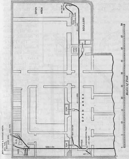
Flgure 208.
At another house it was found necessary to ventilate the drains in direct opposition to the principles laid down above. Figure 209 is a plan of this house. Being situated at the corner of a street and crescent of houses, it was badly designed, the party-wall forming an acute angle with the front wall of the house. The back basement was used as a kitchen, and the only uncovered surface was a small yard about 5 feet square. It was impossible to ventilate the drains at the highest point without fixing the pipes on other people's property, so it was decided to fix the fresh-air inlet at the highest point of the drain, and use the soil pipe, which was fixed inside the sharp angle at the front of the house, as the upcast ventilator. A flushing-tank was fixed in the small back yard, as it was feared that the drain, having a sluggish fall and only dirty water discharge sent down it, would become foul inside. This flushing-tank can be regulated so that it will discharge itself at intervals of time varying from a few minutes to several hours.

Figure 209.
Some engineers say that a fifty or sixty-gallon discharge once or twice in twenty-four hours is the right system to adopt, but I much prefer to have, say, a ten-gallon discharge every two hours. For large houses with long lengths of drainage the quantity might be increased; but with drains well laid, even if in long lengths, ten gallons of water discharged into them through a 4-inch pipe in a few seconds will be found to have a very good effect.
The soil pipe of the house, Figure 209, and which acted as the drain upcast ventilator, was fixed in a recess inside the house, and the hot-water circulation pipes being close by, the heat rarefied the air inside the soil pipe and so accelerated the ventilation of the drains, etc. - in fact, overcame the resistance offered by the rarefied air in the horizontal drain, and which would have a tendency to rise to the highest point where the fresh-air inlet was fixed.
Figure 210 is a plan of a very common description of a terrace house, having two frontages, one on the street and the other on a common garden or lawn, the sides being hemmed in by other houses. One of this kind had to be rearranged after it had been built about nine or ten years. On examination being made it was found that the whole of the soil beneath the basement flooring was saturated with sewage. About fifty loads of earth had to be dug out and carted away. A so-called sanitary engineer had made a few alterations about two years before the writer was sent to see what was wrong, and one of this gentleman's introductions was a cesspool - misnamed a trap, about 3 feet square and 5 feet deep, situated at the point marked A on the plan, Figure 210. This was not sealed down air-tight, and the floor over being of wood, it may be judged that this was a very unhealthy corner. A staircase was immediately over this cesspool, up which the smells used to pass and into the various bedroom windows which looked on to the staircase.
A new 5-inch cast-iron drain was laid through the house in a perfectly straight line, a brick manhole or access-chamber being built at each end, in the front and back areas, so that if a candle was held at one end it could be seen at the other.* There were two stacks of soil pipes, as shown on the plan, Figure 210, fixed in the angles of the staircase, and both were defective and had to be renewed. One was of light iron, and was also used as a rain-water pipe; all the joints were defective. It was impossible to remove the water-closets so that the soil pipes could be fixed outside the house, or the water-closet chambers ventilated through the walls, unless some of the best rooms had a portion partitioned off. So to make them as inoffensive as possible ventilation-shafts were fixed from each

Figure 210.
* If an examination is made during the day-time a glass hand-mirror is as good as a candle to reflect light into the interior of the drain pipes water-closet chamber to a position clear of the skylight over the staircase - see Figure 360.
It was suggested that the drains should have a ventilation pipe carried up from the highest point to the roof, but the occupier objected to have this done.
The only resource left was to make use of the soil pipes to ventilate the drains. Unfortunately, these pipes were in the centre of the house, and, so that the whole of the drains should have an air-current pass through, an inlet had to be arranged at each extremity. An open grating was left in the front area at the exit end of the drain. A similar grating was left in the back area, but it was found that sometimes when hot water was discharged down the scullery-sinks steam escaped through the grating. When this water was that in which vegetables or fish had been cooked, the smell was so unpleasant that a mica non-return valve had to be fixed to prevent any escape.
This mica valve had to be so adjusted that it would open only a short distance, and the open grating in the front area had to be contracted, so that, as nearly as possible, an equal amount of air would pass in at each end of the drain.
The part D was only connected in a temporary manner until the ventilation had been tested, as it was thought probable that it would be necessary to insert a trap, to insure both sections of the drains being thoroughly ventilated, but this was not found to be required, so the joints were made secure.
Continue to:
My Books

