Chapter XXIX. Wash-Hand Basins. Part 4
Description
This section is from the book "Plumbing Practice", by J. Wright Clarke. Also available from Amazon: Modern plumbing practice.
Chapter XXIX. Wash-Hand Basins. Part 4
Besides the traps that have been described there are several others very similar in their action, and there are also what are known as mechanical traps. Some -of these have a flap-valve fixed inside over the outlet pipe. Others have a floating ball or else a weighted ball; these fit over the end of the inlet pipe in the body of the trap, which has to be made in such a way that when out of action the ball covers the orifice. The advocates for these traps claim that they are proof against back-pressure, but there is no back-pressure when the waste pipes are ventilated. These traps all clog up with soapy matter, and this occurs more frequently in districts where the water used is very hard.
Figures 300, 301, and 302, are illustrations of the principles of the flap-valve, heavy, and floating balls, which speak for themselves. The writer, some time ago, had to take out a mechanical trap, as it was continually becoming choked. After it had lain on a shelf for two or three months, it was taken down to show a friend the condition it was in, when it was found that the matter inside had all dried up, and nothing was left excepting what may be compared to coarse-looking cobwebs. A piece of waste pipe, 1 1/2 inch in diameter, which had become choked with soapy curds, was kept as a sample, and, after an interval of time, the matter had all dried up, and only a thin scale was found adhering to, in some places detached from, the sides, and this stoppage had resisted, when it was fixed in its position, the action of a hand force-pump.
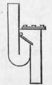
Figure 300.
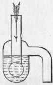
Figure 301.
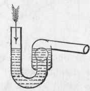
Figure 302.
All wash-hand basin waste pipes should discharge with open ends into an interceptor or gulley trap.
In some town houses, built years ago when little or no thought was bestowed on sanitary questions, and all the fittings are in the centre of the house, it is very difficult to arrange for the waste pipe to discharge into the open air; or the expense of the alteration would be so great that other means have been resorted to. In these cases two traps have been fixed, and a ventilating pipe soldered in the waste pipe between them. This is shown by sketch, Figure 303, at A, and the waste pipe connected to the soil pipe of the adjoining water-closet. When this is done the air pipe must not be branched into the soil pipe, but must be continued separately to a suitable position out-of-doors. If another vent pipe is fixed at B, a current of air can pass through. This is an advantage when the wash-hand basin is some distance away, thus necessitating a long length of waste pipe. When the soil pipe is of lead, and hot water is used in the wash-hand bowl, it will often occur that the soil pipe will break by the expansion and contraction of the metal caused by the hot-water discharges.
There are several manufacturers who make sets of wash-hand basins as shown by Figure 304, which is a front elevation, and.
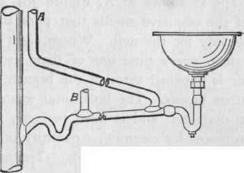
Figure 303.
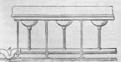
Figure 304.
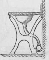
Figure 305.
Figure 305, which is an end view. These are very strong, and suitable for public schools and similar institutions where they are subjected to rough usage, but from a sanitary point of view they are far from being good. As a rule, the trapping of the waste pipe is improperly done. Sometimes no trap at all is fixed, the end of the horizontal waste being continued to discharge over a gulley-trap, or, if fixed upstairs, into the head of a vertical stack of waste pipe fixed outside the house. In these cases a current of air passes from the outside and through the waste pipes. This air may be perfectly pure and sweet when it enters the waste pipe, but when it escapes through the waste or overflow pipes it is rarely in a state fit for breathing. The writer has had to fit traps as shown at A, Figure 304, to several of these sets because of the offensive smells that pass through, but this is little or no remedy for the evil. Where eight or ten basins are fixed in one range, every time one of them is emptied a certain amount of air is expelled through the branch waste or overflow pipes of the other basins. The horizontal waste is generally of iron, 3 inches in diameter, and is fixed perfectly level. On taking these pipes to pieces for cleaning, a quantity of black offensive-smelling matter is generally found inside. Neither is any provision made to prevent the waste pipe from rusting. The branch waste pipes are generally connected at right angles to the main waste. The result of being branched in this way is, that every time a basin is emptied as much water passes toward the stopped end as to the outlet, so that the black matter spoken of is being continually stirred up and moved backward and forward inside the pipe.
Figure 306 is an end view and Figure 307 a front view of one basin out of some ranges designed and fixed by the writer for the young men and women's use at a large drapery establishment. The whole of the horizontal waste pipes and the brackets, etc, were of galvanized-iron. The brackets had projections cast on at C and D, Figure 306, and were firmly fixed to the wall. By doing this the whole of the space beneath was open, and, as nothing touched the floor, there were no corners in which dirt, etc, could accumulate. The horizontal waste pipes had a fall throughout their length. They were fixed immediately beneath the centres of the basins, so as not to have long branch waste pipes. Instead of round openings in the brackets for the horizontal waste pipes to lie in they were made as shown in Figure 306. The highest end of the waste was in the position as shown, but the lowest end was situated as marked by dotted lines. The branch arms, F, F, Figure 307, to receive the wast( and overflow pipes, were all turned in the direction of the current, so as to avoid discharges from the basins running up the main waste. The waste-plugs were locked similar to those illustrated in an earlier chapter, and the unions were socketed into the branch wastes, the joints being made water-tight by the insertion of india-rubber rings. The basins were supported by means of galvanized-iron cross-pieces resting on the brackets, and were so arranged that should a basin get broken, a new one could be substituted without taking away the marble top, or moving it at the risk of breaking it.
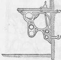
Figure 306.
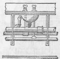
Figure 307.
Continue to:
My Books

