Slop-Sinks. Continued
Description
This section is from the book "Plumbing Practice", by J. Wright Clarke. Also available from Amazon: Modern plumbing practice.
Slop-Sinks. Continued
In a newly-built hospital everything was done that could possibly be required for the use of the doctors and nurses, and comfort of the patients. On each floor are baths and other conveniences. All hot and cold-water, waste, and ventilation pipes are fixed inside the building, and supported every 3 feet on iron brackets pinned and cemented to the wall as shown in elevation, Figure 233. The iron band is made in two halves, and after placing the pipes in position these are bolted together as shown, the pipes all being 2 inches clear of the walls, so that they can be seen and accessible all round. A narrow lead flange is soldered on the lead pipe above each bracket to prevent it slippirg through, and so avoid the necessity of bolting the band up so tightly as to bruise the pipe. Each pipe is painted a distinctive colour, so that there is no likelihood of confusion as to its purpose. For instance, hot-water pipes are painted red; cold, blue; waste, purple; air, white; and so on for other pipes.
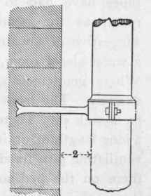
Figure 233.
To allow for expansion and contraction in the bath waste pipes the joints are made as shown in section, Figure 234. In this case the end of the top pipe is slightly coned, and the bottom one opened to receive it. A vulcanized indiarubber cone-piece, with a bead on top edge, as shown in Figure 235, is sprung on the coned end of the upper pipe, which is then placed in its position and socketed into the bottom one. These joints are so flexible as to allow for all variations in length of piping that are likely to arise.
To return to our subject of sinks, these conveniences should be placed in various parts of a house where they would be useful, and so save the labour and toil of having to carry water from a distance and up or down a flight of stairs. At the same time thought should be bestowed on their position. A cupboard or closet in a bedroom is not a good position, or anywhere that injury would be done to the rooms beneath should a pipe break or other leakage arise. The writer has had to do with several cases where the waste pipes have had to be removed when fixed near an important room, as the rushing noise of water was so unpleasant and suggestive of a water-closet. A slop-sink should not be fixed in a water-closet room, or the same doorway used for the two places. Where gentlemen are about, this would be against the laws of decency. The front portion of the house is not always suitable to fix a sink in. There are cases where a sink so fixed has required a long length of drainage brought to receive the waste water, and a ventilating pipe fixed up to the roof. When sinks are fixed here and there on the bedroom floors of a house, and in such a position that each one requires a separate waste pipe down to the basement, previous remarks will cover all that need be said about them, but when they are situated over each other, additional precautions have to be taken with regard to fixing the waste and ventilation pipes.
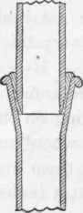
Figure 234.
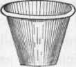
Figure 235.
Slop-Sinks
The reader is referred to A, Figure 236, where the branch waste pipe is soldered into the main stack above the floor-line. This is the right thing to do, it being an economy of material and there being a short length of branch pipe to keep clean, in addition to having no bends in it. But the one on the floor below should be differently connected to the main stack, as it often occurs that discharges from the upper sink will run up the branch pipe of the lower one, which, if fixed as shown, cannot very well happen. But this arrangement brings up another question - that of syphonage. The upper one is secure against this, provided the branch pipe is not very long and the main stack is continued with an open end to act as a ventilator, but the lower end will have the water drawn out of the trap every time a pail of slops is thrown down it by reason of the outlet pipe acting as a syphon. To prevent this a ventilation pipe should be taken from the branch pipe, as shown by dotted lines at B. This should not be less in diameter than the waste pipe. Another use for this vent is that it prevents the air in the waste pipe being so compressed when discharges are sent from a higher level as to burst through the water-seal of the lower trap. One would suppose that if the main stack of waste was open at the bottom end this could not occur, but it is found in practice that it does sometimes happen, hence the necessity of this precaution being taken. Again, this pipe will prevent an accumulation of bad air at the point B, which would be displaced by discharges from the sink, and driven out at the bottom of the waste pipe, to the annoyance of anyone standing near at the time, or the liability of its entering an open window on the ground or basement floor. Instead of carrying this vent pipe from the trap upward, as has been shown, it has sometimes been branched into the vertical waste pipe at C, as shown by thick dotted lines, but this has not been so successful as the other way described. Some years ago the writer fixed a stack of slop-sink waste pipes, and ventilated each trap through the wall. There were four sinks, fixed vertically over each other, and Figure 237 is an elevation showing one of them. But it was found that whenever a sink was used an unpleasant puff of air was driven out, and this would sometimes bring a few drops of water with it. It was also found that only sections of the system had a continuous current of air passing through, the air in the other sections being stagnant, and this would account for the smells driven out at the bottom end of the waste pipes.
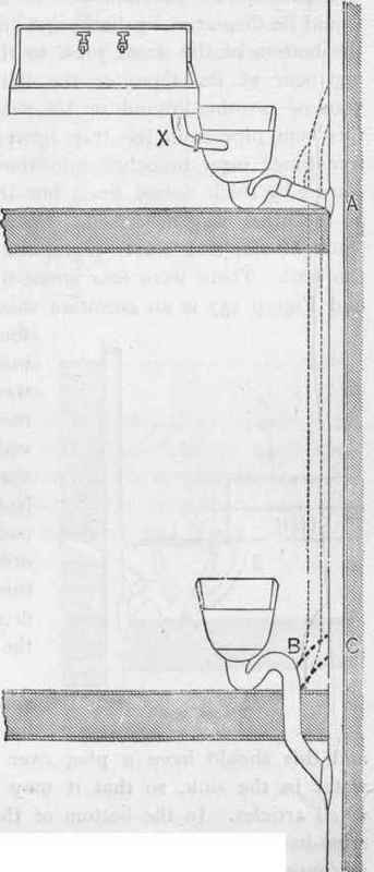
Figure 236.
In addition to the slop convenience it is always necessary to have a sink for drawing water, and this should have a plug over the waste pipe for retaining water in the sink, so that it may be used for washing up any small articles. In the bottom of the plug-washer should be fixed cross-bars to prevent anything getting into the waste pipe to form a stoppage. The waste pipe from this sink does not require any trap. It can be taken into the one under the slop-basin, as shown at Z, Figure 237, or into the arm, as shown at X, Figure 236. The latter is the best plan, as less pipe is required and no stagnant air is displaced when the sink is emptied. The sink also empties quicker, as the air in the pipe does not offer any resistance in the same manner as when the bottom end is sealed with water, as shown in Figure 237. Tinned copper looks cleaner than lead for these sinks. The back side, and, when fixed in an angle, the end as well, should stand at least 18 inches high to protect the walls from splashings and also insure any dribble from a leaking cock falling into the sink. The water service pipes can be brought behind the splash-board, the sink being kept out far enough to allow for that being done, it not being by any means a good plan to bury pipes in the wall. Holes can be made through the splash-board for the bosses to project through, so the cocks can be screwed in afterward. To hide the ragged edge sometimes made when making the holes, or to hide the place should it be made too large, a brass face-plate can be fixed at the same time as the cock. These can be engraved to show what they supply, as shown at Figure 238. At a job recently done there were four cocks engraved "cold," "hot," "filtered," and "soft," fixed to each sink throughout the house.

Figure 237.
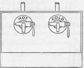
Figure 238.
Continue to:
My Books

