


Processes Dependent On Ductility. Section I. - Drawing Wires, Etc. Continued
Description
This section is from the book "Turning And Mechanical Manipulation", by Charles Holtzapffel. Also available from Amazon: Turning and Mechanical Manipulation.
Processes Dependent On Ductility. Section I. - Drawing Wires, Etc. Continued
Manufacturers in Metal, chapters XIV. and .of which contain much information on wire-drawing and wire-working.
* In actual practice, the riddle is made wider than represented, so as to contain about half a dozen rows of pins suitable to as many sixes of wire; between every set of pins, and fixed close down to the board, is a straight wire about three times the diameter of the one to be straightened: very great importance is attached to this latter or central wire, being itself straight, it serves as a metallic bod for the small wire to run upon, and it thereby gets worn into furrows crossing it obliquely from pin to pin. The board is retained by two staples at the far end, which fit loosely on two studs or nails driven into the work-bench.
It is necessary to be very particular in pulling the wire through, not to allow it to lean sensibly against either of the last two pins, or it will assume a curve; and in this manner, by drawing the wire designedly at different angles, it may be thrown into any required circular arc, instead of the right line.*
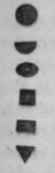
The great bulk of wire is cylindrical, but draw-plates are also made of various other forms, as oval, half round, square, and triangular, for the wires figs. 293; and also of more complex forms, as for the production of steel of the sections of figs. 294, known as pinion wire, the whole of the illustrations being printed from the wires themselves. The largest of 294, serves for the pinions of clocks, and the smallest for those of watches; in these cases the entire arbor, (which carries one of the toothed wheels,) is made of the pinion wire, but the teeth are removed from every part, excepting that which works into the adjoining wheel of the train. The plates for pinion wire are exactly the same as the others in principle, and exhibit a remarkable degree of perfection in their construction, as for every size there roust be a series of many holes gradually assuming the form of a circular foliated Gothic window, with six, seven, eight or more foils.
* Cylindrical shafts may be viewed as large wires, and when they are turned with ordinary care, in a slide-lathe with a back-stay, it becomes pretty certain that the shafts are circular, and of true diameters; but they are frequently more or less crooked or bent when they leave the lathe.
In straightening the axes or shafts intended for the Calculating Machine, which were of steel, about 6 to 10 feet long, and $ to 1 inch diameter, Mr. Clements employed three half-round dies, fig. 292, a, c, fixed to the bed of a fly-press, and b, to the screw of the same, which was so adjusted that b, could only bend the portion of the shaft between a, c, to the limit of its elasticity; and therefore, by keeping the press constantly at work, drawing the rod through, and twisting it round so as to bend it at every point of its length, every shaft was made perfectly straight.
The straightening of black wrought-iron shafts previous to turning, is now accom-plished by three equidistant rollers, say a foot diameter and twelve feet long, similar to fig. 233, p. 389. The shaft is heated to redness, and the center roller is raised at the moment of its introduction, and then a few turns are given to the whole; this straightens the shaft, and retains it so until partially cooled; the other end of the shaft, should it exceed the length of the rollers, is then heated, and treated in the same manner.
All these modes are highly useful, as they operate upon the materials without partially condensing any point, from which unequal treatment a loss of figure would be almost certain to occur, when any such condensed point is partially removed by the turning-tool or otherwise; as it appears to be quite impossible to prevent all sorts of perplexities, when, by any mode of operation, the one point of a material receives a different treatment from the remainder.
Figs.293
294.

295.

296.

Fig. 297.

Some of the printed calicoes and muslins are also curious examples of the wire-drawing process; the pattern fig. 295, consists of no less than 205 different pieces of copper wire of various forms, fixed into a wood block; the surfaces of the wires when filed smooth, are printed from after the manner of printers' types; the few detached pieces, fig. 296, show some of the sections of such wires, and which may be combined in endless variety. In the same manner the specimen of music fig. 297, is printed from the surfaces of detached wires and slips of copper fixed in a wooden block; this is only one amongst the many ingenious processes for printing music by letter-press or surface printing.
Figs. 298

299.

300.


Fig. 298 represents the double-plates or swage-bits used, for some of the pieces in figs. 295 and 297; the dies are fitted into a small frame or cramp with a side screw, (much the same as dies for cutting screws,) so that the metal may be gradually reduced by one pair of swage-bits. This method is very much employed by the silversmith and goldsmith for mouldings, the tools being much cheaper than rollers: the piece 299 was thus prepared for the edging of silver and gold boxes; it is bent round to the form of the box or cover, whether square, circular or oval, and the rebate on the straight side of the band serves for receiving the flat plate to constitute the cover.*
The window lead, shown in section in fig. 300, does not admit of being drawn in the ordinary manner, from the softness of the material, nor of being rolled, because of its undercut section; the two principles are, therefore, curiously combined in the glazier's vice. It may be conceived that the shade lines of 301, represent parts of two narrow rollers with roughened edges, (equal in thickness to the glass,) which indent the bottom of the groove, and thereby carry the lead between the figured side-pieces s s, one only shown. In some cases cutting is combined with drawing, cutters are then fixed to the draw-plate, this method has been adapted to making rules and similar rods; and in perfecting the flattened wire for the reeds used in looms, the edges are rounded by reeling the wire beneath a forked cutter, a process intermediate between turning and planing.
The process of wire-drawing is seldom practised by the general mechanician, and still less by the amateur; but when it is necessary to produce a wire either of some unusual section not prepared by the manufacturer, or that the equality of size requires more than usual exactness, the process may be accomplished in the small way, by fixing the draw-plate in the tail-vice and drawing the wire through with the pliers or a hand vice, or by a reel moved by a winch handle.
* The most perfect example of this application of the drawing process is in the British Mint: two fixed rollers are employed after the manner of a draw-plate, and the long strip of gold or silver, when rolled very nearly to the thickness, drawn through the stationary rollers, by dogs attached to one of the links of an endless chain which is in continual motion from the steam-engine. It was found barely possible to make the surfaces of revolving rollers so truly concentric that the equality of thickness in the metal could be obtained with the rigorous exactness required, so as to dispense entirely with the necessity of scraping every piece individually, a mode still practised in some of the Continental mints.
The metal, when drawn, is tested by punching out one blank at each end; these are carefully weighed, and if found correct, the whole strip is punched into blanks; and such is the accuracy of the drawing and punching processes, that without the smallest after-adjustment, any fifty or one-hundred blanks weigh alike to the fraction of a grain. See further, page 938, vol. ii. This beautiful arrangement was invented by the late Sir John Barton, then Comptroller of H. M's. Mint.
Continue to:


My Books

