Plumbing In A New England Residence
Description
This section is from the book "American Plumbing Practice", by The Engineering Record. Also available from Amazon: Plumbing: A working manual of American plumbing practice.
Plumbing In A New England Residence
(Published In 1896.)
In designing and executing the plumbing of the new house of Mrs. Edward Perkins, of Hartford, Conn., it was intended to make the work as complete, simple, efficient, and durable as possible, and to provide very carefully for its operation and maintenance. The accompanying illustrations and description are intended to show the general plan, methods, and workmanship adopted for this purpose. The number and location of fixtures, their style and arrangement, and the storage distribution and control of the hot and cold water supply were not unusual, but the principal features of the waste and vent systems and the materials, proportions, and workmanship of the whole installation are shown by the following drawings and description, prepared from the original designs.
Figure 1 is a basement plan showing connections of soil and waste pipes to the main drain, and indicating by dotted lines those pipes which are on the ceiling or are buried, those on the cellar floor being shown in full. The different cleanouts, traps, and air pipes, leaders and tile drains are also noted on the drawing to show the thorough provision for the flow and ventilation, and for access to all parts of the system to remove obstructions if necessary.
Figure 2 is a small-scale plan of the second story, merely intended to show the position of the fixtures, which in general were served by adjacent stacks of vertical pipes, not here shown.
Figure 3 is a partial vertical section at Z Z, Figs. 1 and 2, showing an elevation of the main stack of soil pipes and most of the fixtures.
From the street sewer a 6-inch salt-glazed Akron hub and spigot earthenware drain is laid, with continuous grade of not less than 1 foot in 10 feet, and jointed with Alsen's neat Portland cement, each joint being thoroughly swabbed out. All pipe lengths bear throughout on the body of pipe, pockets in trench being cut for hubs. No stones or rock were allowed to come within 12 inches of the pipe. The backfilling was well rammed for each 12 inches in depth filled. At the property line a running trap was set, and a clean out and 5-inch iron fresh-air inlet and sewer vent, one on each side of the trap, were carried 18 inches above ground, and finished with one-quarter bends and brass-bar gratings screwed into the bends. Four-inch earthenware branches were connected for the rainwater leaders. Outside of the house this pipe connects with a 5-inch extra-heavy iron drain with the Y on the house sewer. In the cellar there is also a running trap, with a heavy brass cleanout on the house side, an iron plug on the sewer side, and a 4-inch fresh-air inlet, extended 30 feet or more from outside of the house, and turned up 18 inches above the ground, with a one-quarter bend and a brass-bar grating. An 8x8-inch brick pier was built at the base of each vertical column, and the pipe was supported solidly on the pier. All branch connections are Y's and one-eighth bends or TY's. Y-branch connections are well turned up. The floor openings were all cut from the top to the bottom of every column before the vertical pipe was put in. All openings in floors and ceilings about lines of pipes are entirely closed and packed with mineral wool so as to entirely seal the opening. All pipes at the roof are flashed with heavy copper, with slip-collar joint clamped to the pipe to allow for expansion. The rainwater leaders are connected in the cellar to the area drains, using an extra-heavy cast-iron ending 2 feet above grade for the leaders. The leaders and area drains have independent extra-heavy cast-iron traps inside of the cellar wall, with heavy brass cleanouts on the house side of the traps, which have not less than 3 inches of water seal. All wrought-iron pipe and fittings are galvanized. The water pipes are of "Standard" pipe, factory-tested to 300 pounds per square inch. All wrought-iron drain, waste, and vent pipes are " extra strong." Pipe up to 1¼ inches diameter is butt-welded, and the larger sizes are lap-welded. All water pipes and fittings are standard galvanized iron. Ground brass unions were used at frequent intervals to admit of ready repair.
Bedroom basins were particularly required. The entire waste system from these basins is quite independent of the drains connecting with the sewer.
The main waste from these basins discharges over an earthenware flushing rim slopsink in the cellar, provided with flush tank. The basin waste main at the sink is trapped and provided with an independent 3-inch fresh-air inlet extended 30 feet outside of the house. The basin waste branches are all vented to the roof, forming a complete vented system of basin wastes entirely cut off from any connection with the sewer or sewer-connected drains.
The cellar underdrains connect into a deep-seal anti back-pressure trap in a brick pocket below the cellar floor. The discharge from the back-pressure trap connects back of a rain-leader trap and has a weeper from the cellar slopsink flush pipe, which will keep both the anti back-pressure trap and rain-leader trap supplied with water in case of drought, and will prevent evaporation of the seal in those traps. Stoppage in the waste beyond leader trap will be announced by flooding at the area drain at the foot of the steps leading to the cellar. Backflow into the under-cellar drains will be prevented by the anti back-pressure trap.
All threaded pipe work is put together with red lead. All lead soil, waste, and vent pipe is drawn pipe of the best quality, and of the following weights per lineal foot.
Diameters. | Weight per Foot. | ||||
½ | inch | ................. | 1 | pound. | |
¾. | " | ................... | 1 ¾ | " | |
1 | " | ................. | 2 | " | |
1½ | " | ................ | 3½ | ." | |
2 | " | ................ | 4 ¾ | " | |
3 | " | .............. | 7 | " | |
4 | " | ..................... | 8 | : | |
All connections of lead and iron pipe are made by " heavy " brass ferrules of the same size as the lead pipe, threaded and screwed or calked into the hub of the iron pipe. All hot and cold supply pipes at fixtures have 12 inches extension beyond faucets or branches to prevent water hammer. The following
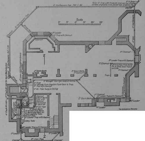
Fig.!.
Basement Plan size branches were provided for fixtures: Laundry-tubs, ¾-inch; water-closets, ½-inch; slopsink, ¾ -inch; pantry sink, 54-inch; kitchen sink, ¾ - inch; bathtubs, ¾ - inch; basins, ½-inch; dark-room sink, ¾-inch; sill cocks, ¾-inch. All stop cocks and valves throughout the building have nickel-plated brass tags with their number neatly stamped on them. All cold pipes in the kitchen and elsewhere where the pipes will "sweat " are painted three coats of white lead and shellac. The photographer's wood sink and 18-inch back was made and set by the carpenter, and is 36x18 inches deep, with a shallow gutter at the back drained to the outlet, with a ¼-inch pitch in the bottom of the sink. The sink and the 18-inch back were lined by the plumber with four-pound sheet lead. The sink has a large ash drain-board and rim, and two ½ - inch brass compression cocks 9 inches from each end of the sink. The cocks are provided with 18 inches of % inch rubber hose wired on. All basins except bathroom basins connect with 2-inch extra-strong galvanized wrought-iron waste columns extended 3 feet above the roof, increased to 4 inches at the roof, with expansion copper roof flashing joint. The basin waste columns connect in the cellar with a 3-inch extra-strong galvanized wrought-iron waste main hung to the first-floor beams and discharging over the cellar slopsink. The waste main has a 3-inch running trap and an independent 3.inch fresh.air inlet extended 30 feet outside of the house wall, with a one-quarter bend and a grating 18 inches above ground. The basin traps on this system are returned vented into their respective waste columns. The trap for the third-floor dark-room sink has a 3-inch water seal. At the points shown on drawings-heavy brass screw-cover cleanouts are provided. All brass trap and fixture fittings and water-closet back airs have ground brass fittings. No washer couplings or fittings are used.


All of the soil, waste, drain, and vent pipes were tested by the plumber in the presence of the engineer by a water-pressure test, and upon final completion of the work and after all fixtures were set and in-working order the smoke test and the peppermint test were applied satisfactorily to the entire system of drains.
The list of fixtures is as follows:
Basement. | First Floor. | Second Floor. | Third Floor. | ||
Water-closets ........ | 1 | 1 | 1 | ||
Baths ............... | 1 | 1 | |||
Basins .............. | . | ., | 6 | 1 | |
Sinks ........... | 1 | ||||
Slopsinks ........... | 1 | 2 | 1 | ||
Laundry tubs ............ | 1 set of 3 | •• | •• | •• |
The above work was designed and supervised by Mr. Albert L. Webster. C. E. New York.
Peabody & Stearns, of Boston, were the architects, and the installation was made by W. H. Spelman & Co., of New York City.
Continue to:
My Books

