Chapter XXXIV. Soil Pipes. Part 4
Description
This section is from the book "Plumbing Practice", by J. Wright Clarke. Also available from Amazon: Modern plumbing practice.
Chapter XXXIV. Soil Pipes. Part 4
Plumbers' work done about twenty years ago, and which recently has had to be taken out, has very often been found to be of good materials and workmanship, but badly arranged. In first-class work it was usual to branch waste pipes from all kinds of fittings into the water-closet trap. Figure 369 is a sketch of a trap with four ends of waste pipes attached that was taken out a short time ago. A was the waste pipe from the lead safe on the floor under the water-closet, B was that from the cistern fixed over the water-closet, C was the waste pipe from a wash-hand basin, and D from a small sink fixed on the floor above.
Figure 370 is a sketch of some old work recently taken out of a building in Lincoln's Inn Fields. It transpired that this job never had worked properly, although a plumber, about two years ago, took out an old D-trap from under the water-closet and fixed one of a better description. In the figure, E is a sink in the scullery; L, a bath; F, a small sink on floor of staircase landing; G, waste pipe from water-closet safe; I, waste pipe from cistern over water-closet; H, the water-closet trap; K, the joint of trap to branch soil pipe, soldered on the top side, and red-lead cemented on the under side. The whole of this work was fixed in the caretaker's apartments on the top floor. Every time the water-closet was used puffs of foul air were sent out of the various waste pipes, and when the scullery sink was used, dirty water would flow up into the bath and the sink on the floor. The caretaker, to prevent this, corked up the bath and sink waste pipes, the corks being removed when those fittings were used. After doing this he was continually sending for the plumber to unstop the waste pipe from the sink E. Very little comment is necessary; the veriest tyro will see at once the stupid arrangements. It may be added, however, that when the waste pipes from L and F were corked up, the horizontal waste pipe would become air-bound by reason of its being trapped and retaining water in the bagged parts. Before the branch pipes were corked the pent-up air could escape, and thus allow the waste water to escape past. Several instances of this kind of botch-work could be given, but the writer refrains, thinking that perhaps his readers would be under the impression that their credulity was being drawn upon.
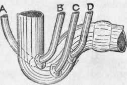
Figure 369.
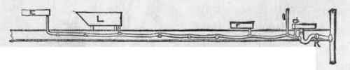
Figure 370.
To return to soil pipes. Figure 371 is a plan of horizontal soil pipes for water-closets which had traps attached to the apparatus. The writer was working with several other plumbers, about eighteen years ago, at a large public hospital where several ranges of water-closets had the soil pipes fixed as above plan. The vertical soil pipes were of lead 6 inches in diameter, and continued to roof as ventilators. The horizontal pipes were 5 inches, and the branches were 4 1/2 inches in diameter. The floors were fire-proof, and, so that they should not be impaired or weakened by cutting any part away, it was decided to fix the branches as shown, in preference to having one horizontal pipe to each range of water-closets, for the reason that little or no fall could be given to a long length of pipe unless a step up was made to the water-closets. Steps should be avoided as much as possible to all water-closets, more especially in a hospital for sick people.
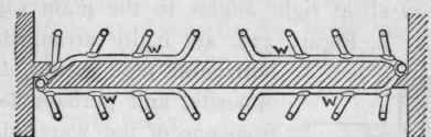
Figure 371.
Figure 372 is a plan of several soil pipes that were fixed in the same hospital where it was required to have two water-closets side by side. In this case there were four floors, the same arrangements being carried out on each. The seats were arranged as shown by dotted lines. That on the right-hand side had to be kept forward, otherwise the flap would not remain open because of the splayed angle of wall. Figure 373 is an elevation; Figure 374, a plan; and Figure 375, a section on A B of a range of water-closets fixed several years ago at a London railway-station for the use of the passengers. The water-closets were on a level with the platform, which was about 40 feet above the level of the street. The reader is referred to the branch-joints, which are all at right angles to the main soil pipes. The branches at X, Y, Figure 373, are badly arranged, as what came down one horizontal pipe would doubtless rush up the one opposite, and perhaps lay there until a discharge from one of the water-closets on that branch would again wash it up into the first one. Similar work was being done at another station by different men, when the above evil was foreseen and precautions taken to prevent what has been described from occurring. Figure 376 is a plan, and Figure 377 an elevation, showing how, in this other case, the branch-joints were made good to the vertical pipe. It will be seen that it was impossible for matter to rush down one pipe and up the one opposite. In addition to the branch pipes being jointed to the vertical pipe at different levels, they were arranged so that they entered at the front side, or nearly so. At Z, Z, Figure 377, is shown how the branches were made good to the horizontal soil pipe, the bottom ends being bent so as to direct the current in the proper direction. There is no doubt that those shown in Figure 373 would cause the stream of water and faecal matter to be directed on the bottom of the horizontal pipe in such a way that part would be driven up the pipe, where it would lay until a discharge from a fitting higher up would send it down again. The illustrations, Figures 371, 372, 373, 374, 375, 376, and 377, are all of soil pipes prepared to receive water-closets that were made of one piece of earthenware - that is, the trap and basin were combined
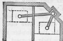
Figure 372.
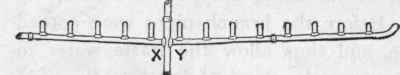
Figure 373.
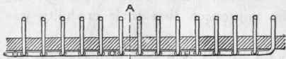
Figure 374.
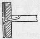
Figure 375.
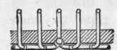
Figure 376.
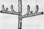
Figure 377.
Continue to:
My Books

