Turret-Lathe Operations. Continued
Description
This section is from the book "Machine Shop Work", by Frederick W. Turner, Oscar E. Perrigo, Howard P. Fairfield. Also available from Amazon: Machine shop work.
Turret-Lathe Operations. Continued
First Operation
The wheel is chucked as shown at A on the inside of the rim, by the chuck-jaws B, This leaves the outside of the rim clear for the turning tools. The cored hole is first rough-bored with the cutter N in the end of a boring bar M, which is held in a steady rest or drill-support D. The hole having been rough-bored, the boring bar M is withdrawn, and the steady rest D thrown back out of the way. The turret is rotated so as to bring the boring bar M1 into position. The forward end of this bar is supported by a bushing H in the main spindle. The two cutters N1 and N2 are for roughing out the hole preparatory to using the taper reamer Q on another face of the turret. While boring with the bar M1 the scale is broken on the web and hub by the tool-post tools shown at J and K. The scale on the periphery is broken by the tool J. The turret is revolved so as to bring the taper reamer Q into position, and the end of its bar enters a bushing in the main spindle. A taper bushing C is inserted in the taper hole for receiving the supporting arbor or pilot T in the facing head, as shown at the top of the engraving. The balance-wheel is rough-faced, and the outer surface of the rim turned with the cutters E, G, H, and F in the facing head. This brings the piece approximately to size. For finishing these surfaces, the cutters G1, E1, H1, and F1, in the finishing head are used, this head being supported in the taper bushing C1. The finishing cuts are very light.
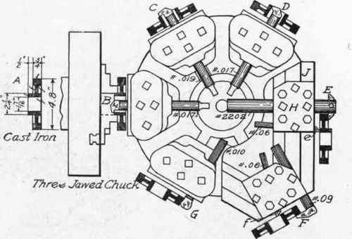
Fig. 310. Arrangement for Machining Spur-Gear Blank.
Second Operation
These cuts being completed, the balance-wheel is removed from the chuck, reversed, and again placed in the chuck, which has in the meantime been equipped with slip jaws of soft metal, bored out so as to exactly fit the curvature of the wheel. The piece is still further supported by a tapered arbor projecting from the hole in the main spindle and accurately fitting the taper-reamed hole. The turret is equipped with tools similar in form and purpose to those described. The scale is broken by tools in the rotating tool-posts, as in the first operation. The first set of tools rough off the face of the rim and hub, and face the web. The second set finishes these surfaces completely, and the operation is completed. The operations for machining a spur-gear blank are well shown in Fig. 310. In this case a flat turret is used on the machine shown in

Fig. 311. Turret Lathe Arranged to Machine Outside of Cone Pulley.
Fig. 299. At A is shown a section of the finished piece of work, giving the actual dimensions. The casting is chucked by the hub, as shown at B. At each of the other five faces the piece of work is represented as mounted, with the tool arranged in proper relation to it to make the required cut. The rough boring having been completed, the turret is revolved to the next face, and the hook tool C faces the back of the hub. Upon the next turn of the turret, the boring tool D makes a finishing cut in the bore, bringing it to an exact diameter. Another turn of the turret, and the bar E, with its inside facing cutter, faces the rear side of the rim, while a facing cutter e faces the front of the hub. It will be noticed that the tool-holder H travels along the slide J, thus providing for the necessary feed for both the tools E and e. The next movement of the turret brings into action the finishing tools F and f, which finish the rear face of the rim and the front face of the hub, operating in a similar manner to the tools E and e. A final turn of the turret brings the round-nosed turning tool G into position, and turns the outside diameter of the gear blank, completing the operation. Upon this machine, provided with the tools shown and operated as described, an iron casting of the dimensions given can be completely machined by an expert operator in from eight to ten minutes. The same work done upon an engine lathe would require four or five times as long.
A much more complicated series of operations is presented in Figs. 311 and 312. In Fig. 312 is shown the first of the series of operations, comprising the machining of the inside of the cone. In Fig. 311 the series of operations necessary to finish the outside are shown. Referring to Fig. 312, it will be seen that the cone-pulley casting A is supported upon the second step from the small end by the cylindrical base B. Within this the three jaws of the chuck grasp the smallest step of the cone, holding it very rigidly and securely in place. The boring bar C carries the cutters for rough-boring the cored hole. Its inner end is supported by a bushing in the main spindle, as shown in Fig. 309. The next turn of the turret brings the boring bar D into action, which finishes the hole to the proper diameter. The next tool E faces the edge of the rim on the largest step of the cone. The face F of the turret carries no tool. Tool G is a very important, compound tool whose work is to finish the inside of the larger three steps, and also to face the annular surfaces between the steps. It consists of a massive casting, bolted to the turret face and divided into three double-ended arms, each of these ends carrying a tool of proper form for the inside turning and facing, making six tools in all. Through the center of this tool-holder is an arbor or steadying bar g, which passes through the bushing in the main spindle and holds the tool-carrier steady and in its proper central position. The tool H serves to finish the inside of the largest step, for a short distance from the face, to the accurate diameter for fitting the flange that supports this end and furnishes a hub through which its shaft or spindle passes.
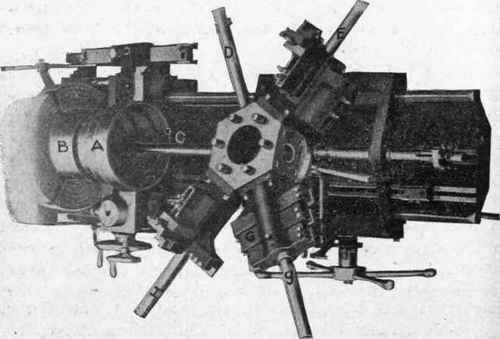
Fig. 312. Arrangement for Machining Inside of Cone Pulley.
The second series of operations is shown in Fig. 311. These operations consist of machining the outside of the cone-pulley casting A, that portion of the inside of the larger end finished by the tool H in the first series of operations fitting over a circular disc B, through slots in which the chuck jaws are forced outwardly against the cone casting. In fixing the casting in position, an arbor C projects from the bored hole, and is entered in a reamed hole of the same diameter in the centering fixture D attached to the turret, whereby the outer end of the cone-pulley casting is quickly and accurately centered. This fixture also serves as an excellent support for the outer end of the cone during the process of turning and facing the outer surfaces. The special revolving tool-block E carries on one side five tools for turning the outside of the cone steps, as shown in the illustrations, and, on the opposite side, five facing tools for facing the annular surfaces between the steps. In the operation of turning the outer surfaces, it is necessary to crown them-that is, to make the center of each step of slightly larger diameter than at the two edges, as in ordinary pulleys. To accomplish this, the taper attachment F is brought into use, being set to give the larger diameter on the side toward the chuck and turning half the width of the outer surface; the setting is then reversed for turning the other half. As all five surfaces are turned or faced simultaneously, the operation is very rapid when compared with the work of an engine lathe. The inside of the small end of the cone is finished with the tools G and H in the usual manner. In all turret operations, the lateral travel of the turret is controlled and limited by the revolving multiple-stop device at J.
There are many devices and adjunct fixtures in use upon the turret lathe; and their number, as well as the ingenuity of their design and the extent of their usefulness, is constantly increasing. So numerous are they that no attempt is here made to show and describe them. The same, in a lesser degree, may be said of the turret-lathe tools. At the same time, there is a very large range of work constantly done on turret lathes with the most ordinary equipment. It was formerly assumed that the turret lathe could be used with economy only when at least a hundred pieces were to be machined. It is ordinary practice at the present day to use the turret lathe when as few as a dozen pieces (and sometimes less) are required. As the value of the turret lathe and its efficiency come to be better understood, its usefulness is better realized and appreciated.
Continue to:
My Books

