A Scheme Of Work: Metal Appliances
Description
This section is from the book "Handcraft In Wood And Metal", by John Hooper, Alfred J. Shirley. Also available from Amazon: Handcraft In Wood And Metal.
A Scheme Of Work: Metal Appliances
Object And Uses
A course of graduated models; introducing many processes and arranged in order of difficulty.
The Joints
The methods of joining metals involved in the various models are as follows: Nos. 3 and 4 riveted joints; No. 8 plain lap and solt-soldered joints; No. 10 brazed lap joint; No. 11 tenoned and riveted, halved and riveted joints; No. 12 butt and clipped joint.
The Processes
No. 1. A Grinding Gauge.-Is used for testing the angles of tools, 110° and 6o° for drills, 60° for chisels and centre punches, 700 and 8o° for turning tools.
It should be made as follows: Use No. 12 I.S.W.G. iron; mark out with a brass scriber, cut out with a chisel, leaving the lines just showing, file down to the lines, using bastard files. Test with try square, protractor, and bevel, or with a bevel protractor. Face up on both sides with bastard and smooth files. Centre punch and drill hole, fine finish face and edges with emery cloth held or glued on a flat piece of wood. Lay gauge on a polished iron surface and punch figures to indicate size of angle with figure punches.
No. 2. A Diamond-pointed Drill.-Draw out, cut off to length, file up to shape, harden and temper to a dark brown; grind cutting edges up on grindstone.
No. 3. Outside Calipers.-
1. Make a drawing of the calipers to the size required.
2. Make a tracing of one leg and transfer to a piece of thin metal for a templet by means of carbon paper, or chalking the back of the tracing, laying on the metal, and going over the lines with a bone point.
3. Go over the lines on the metal with a scriber.
4. Centre punch the centre of joint and describe the circle with compasses, then cut out the templet, working to the drawing as accurately as possible.
5. Mark out with a brass scriber on No. 12 I.S.W.G. iron the two legs, using the templet just made.
6. Cut out with a chisel, leaving the line in.
7. Drill a small hole in the centre of each joint of the legs and slip them on a pin.
8. File up both legs while they are together on the pin.
9. Flatten the legs and face them up both sides with bastard and smooth files.
10. If right sized washers cannot be obtained make them from the same material as that used for the legs.
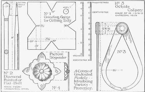
Fig. 6.-A suggested course of models.
Fig. 6, No. 3 (continued).
11. Cut off a piece of § in. round iron for the rivet, square the ends and anneal it.
12. Drill the holes in the legs, and the washers to fit the rivet, and counter-sink the holes on the sides that will be outwards.
13. Put rivet in position and burr over with a light hammer completely filling the countersinking.
14. Face off the outside of rivets and fine finish the calipers with emery cloth. No. 4. Picture Suspender.-The back should be made from 16 I.S.W.G.
and the rose from 18 or 20 I.S.W.G. metal. The fluting of the rose could be left out if necessary.
1. Make templets for back and rose.
2. Mark out the back, using templet.
3. Cut out and file up to shape.
4. Mark rose out on metal, place on the pitch, and work it up from the back and front with punches.
5. Cut rose out and drill holes in back and rose, and anneal the rivet.
6. Polish, stain, and lacquer as required, including the rivet.
7. Rivet together by placing rivet in a hollow tool which is held in the vice.
Fig. 7, No. 1. Cold Hand Chisel.-Should be made from hexagonal tool steel.
1. Take a convenient length of steel and draw out the point.
2. Cut off to length.
3. Trim up the end, and file cutting edge to correct angle, using the grinding gauge.
4. Harden and temper cutting end to a dark brown.
5. Finish off on emery bob.
No. 2. Finger Plate.-Could be made from 12, 14, or 16 I.S.W.G. material.
1. Cut off the material to the correct size.
2. Engrave the line, face up, then go over line again.
3. Set out the ornamental top, raise it on a lead block, cut it out, drill the holes.
4. Fit ornamental top to the plate mark off the holes and drill the plate, slightly countersinking the holes at the back, drill fixing holes.
5. Polish, colour, or lacquer as required.
6. Put top on to plate; put rivets in, one at a time, holding rivets in cup tool and lightly burring over at the back.
No. 3. Steel Scriber.-Should be made from 1/4 in. square tool steel.
1. Cut off material and draw down both ends as shown in Fig. 2.
2. Cut off to correct length. Bend one end at right angles (Fig. 3).
3. Make eye, Figs. 4 and 5.
4. Twist centre as shown in Fig. 2, p. 74.
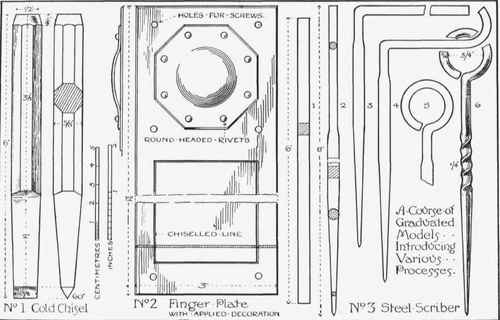
Fig. 7. - A suggested course of models.
5. Clean up, harden and temper point to a dark brown, if for use on soft metals to a light brown.
Fig. 8, No. 1. A Rectangular Box.-No. 22, 24, 26, 28 I.S.W.G. sheet metal should be used for this.
1. Set out the development of the body and the lid on the metal.
2. Cut them out clean with the shears.
3. Bend up to shape, using a folding machine, bending clamp , or a hatchet stake.
4. Tack the bottom part in a few places with solder and soldering iron; examine it for squareness, etc., then solder the seams neatly together.
5. See the lid fits true, then solder the seams neatly.
6. Wash well in potash and hot water and dry out in sawdust.
7. Polish if required.
No. 2. A Pin Cutter.-Size of material to be used depends on the size of the cutter; the one illustrated could be made from 3/8 in. square tool steel.
1. Spread end for cutter with top fuller.
2. Round the shank and cut off to length.
3. Draw down the taper square.
4. File the cutting end to the correct shape.
5. Harden and temper the cutting end to a dark brown.
6. Finish cutting end on grindstone and gloss up on emery bob.
Fig. 9, No. 1. A Corner Clamp.-No. 18 I.S.W.G. metal would be suitable for this.
1. Set out development on metal.
2. Punch the holes.
3. Cut out to shape.
4. Bend to correct angles, and see the corners where they overlap lie close together.
5. Braze the corner and clean off with a file.
6. Finish as required.
No. 2. An Iron Grille.-Used for protecting windows.
1. Make a drawing to the size required.
2. Cut off all the material a little longer than is actually required.
3. Make the frame by setting out all the necessary holes and drilling them.
4. Make the tenons on the various bars by sawing down and filing, and fit them tightly to the holes, seeing that the shoulders come up square. Check sizes.
5. Twist the centre bars. Note, two right handed and one left handed.
6. Mark off and make the halved joints; see they fit together neatly.
7. Drill the holes in the halved joints for the rivets, anneal them, and rivet all centre part together.
8. Put on the frame, riveting corners up first.
9. Rivet up other tenons, and trim off excess metal.
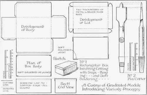
Flg. 8. - A suggested course of models.
Fig. 9, No. 2 (cotitinued).
10. Coat with boiled oil which should be applied boiling hot. ii. Paint the colour desired. No. 3. A Ring Drop Handle.
1. Make a drawing to the required shape and size.
2. Make templet of back-plate.
3. For the handle shown 1/4 in. round for the ring and No. 14 I.S.W.G. for the back-plate would be suitable.
4. Raise centre of back-plate, punch slot hole for the clip, then cut out to shape, marking this off the templet.
5. Bend up ring, file the pin, and make the clip as illustrated on p. 74.
6. Fit clip and ring to slot-hole, and see that it hangs square and at an equal distance from the back-plate.
7. Drill screw holes, in back-plate and smooth it up if necessary.
8. Chamfer back-plate.
9. Polish, colour, and lacquer back-plate and ring.
10. Put together, and tightly bend over the clip.

Fig. 9. - A suggested course of models.
Continue to:
My Books

